11. Input Devices
-
Individual Assignment
- Measure something: add a sensor to your micro-controller board
-
Group Assignment
- Probe an input device’s analog levels and digital signals
Individual Assignment
Input Device Choice
Force Sensing Resistor (FSR) was chosen. In particular Square FSR) - Interlink 406. This sensor is an Interlink model 406 FSR with a 38mm square sensing region.
Note
This sensor can’t detect where on the square you pressed
Overview
Originally from Overview.
FSRs are sensors that allow you to detect physical pressure, squeezing and weight. They are simple to use and low cost. The FSR is made of 2 layers separated by a spacer. The more one presses, the more of those Active Element dots touch the semiconductor and that makes the resistance go down. FSRs are basically a resistor that changes its resistive value (in ohms Ω) depending on how much it is pressed. These sensors are fairly low cost, and easy to use but they’re rarely accurate. They also vary some from sensor to sensor perhaps 10%. So basically when you use FSRs you should only expect to get ranges of response. While FSRs can detect weight, they’re a bad choice for detecting exactly how many pounds of weight are on them.
- How to measure force with an FSR?
The FSR’s resistance changes as more pressure is applied. When there is no pressure, the sensor looks like an infinite resistor (open circuit), as the pressure increases, the resistance goes down.
Testing an FSR
The easiest way to determine how your FSR works is to connect a multimeter in resistance-measurement mode to the two tabs on your sensor and see how the resistance changes.
Probing an SFR’s analog levels.
See Testing an FSR for more information
Note
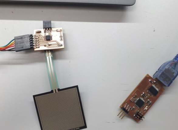
It is possible to solder onto the tabs but it might melt the plastic and ruin the FSR! Therefore, the FSR was connected to the board using a terminal block. A board was designed and fabricated to accommodate the FSR.
Using the FSR
The easiest way to measure a resistive sensor is to connect one end to Power and the other to a pull-down resistor to ground. Then the point between the fixed pulldown resistor and the variable FSR resistor is connected to the analog input of a micro-controller such as in the board designed in the next section.
Later on, a sketch was used to take the analog voltage reading … it does not do any calculations, it just prints out what it interprets as the amount of pressure in a qualitative manner.
Electronic Design
-
A board for hosting the FSR was designed. It Uses Microchip Technology ATTINY412-SSNR.
Schematic
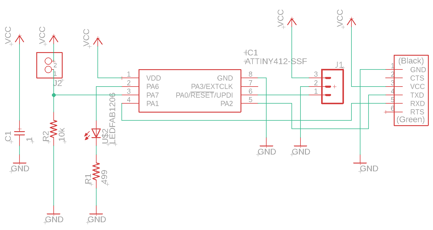
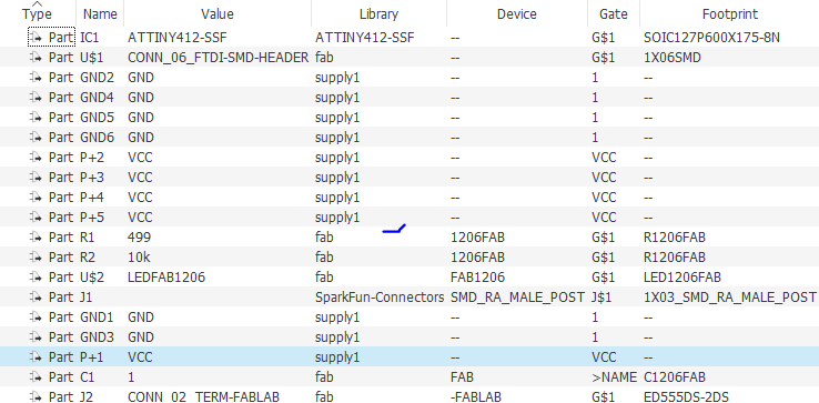
Components
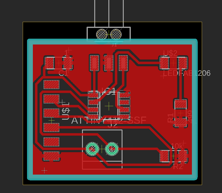
Board
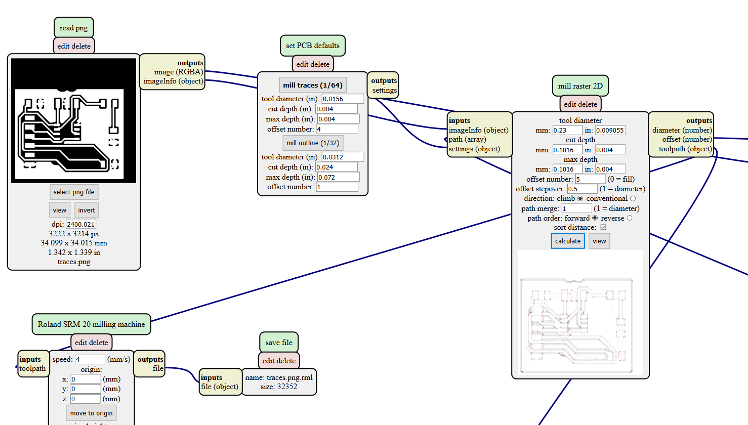
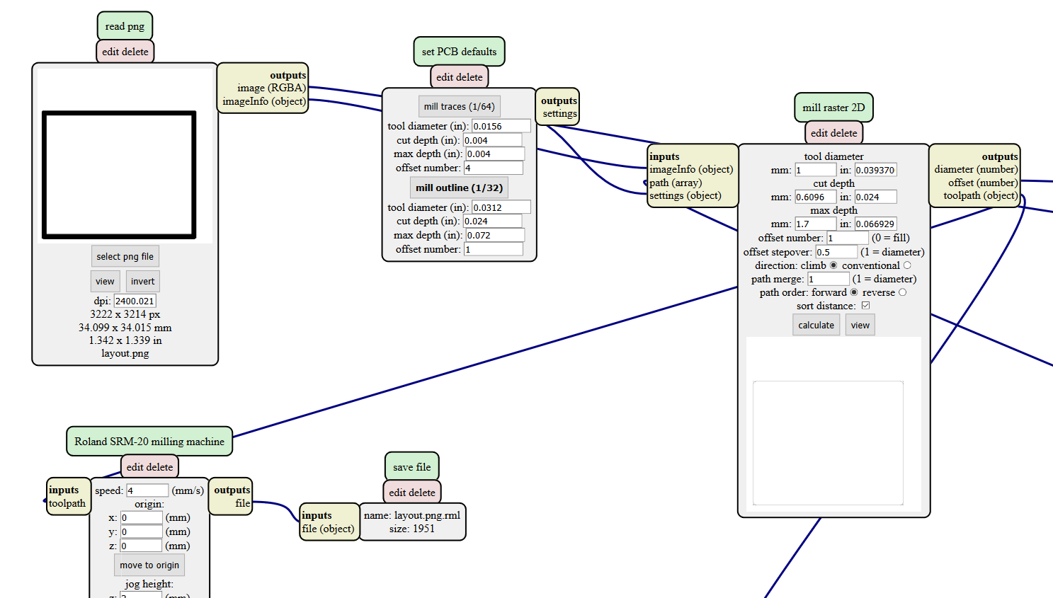
Machine Preparation
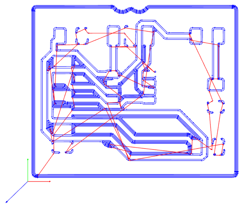
Traces
Traces preparation using mods.
Traces output view using mods.
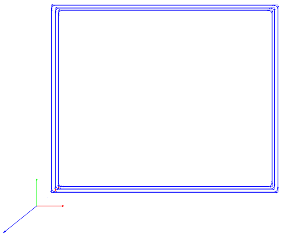
Outline
Outline preparation using mods.
Outline output view using mods.
Production
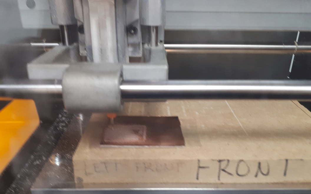
Milling
Board Milling.
Using Hand drill for milling holes for the connector.
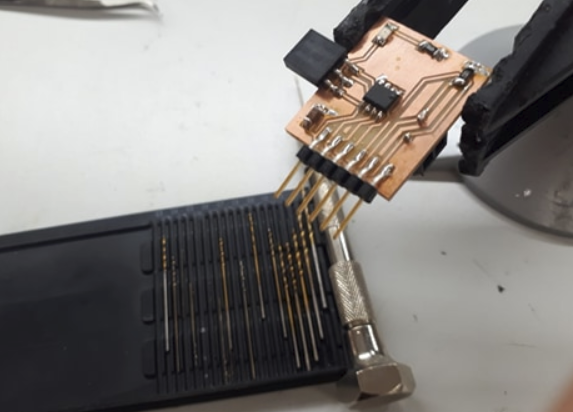
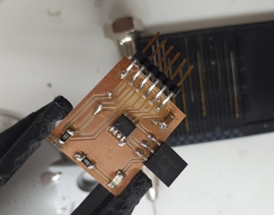
Soldering
Board Soldered.
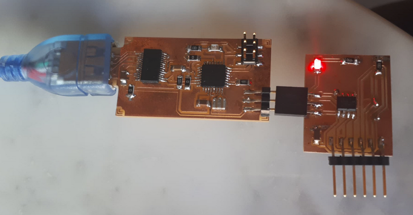
Programming
Board Connected to Programmer.
Uploading sketch to Board.
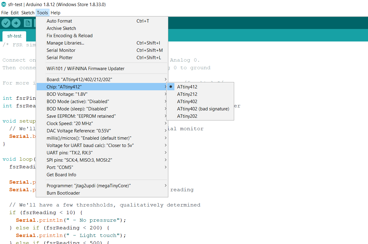
Code Execution
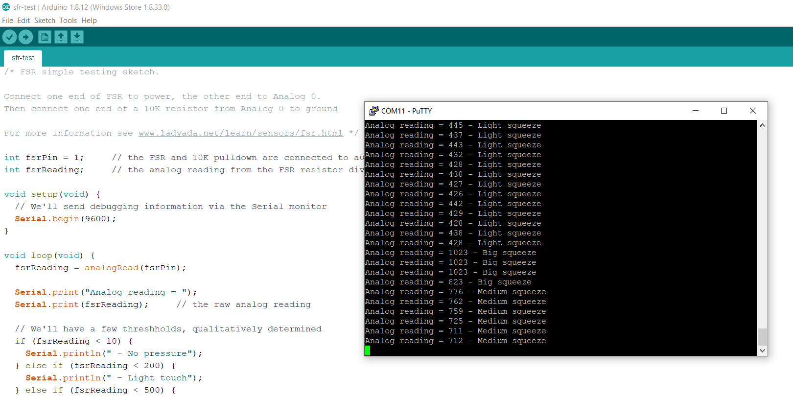
/* FSR simple testing sketch.
Connect one end of FSR to power, the other end to Analog 1
Then connect one end of a 10K resistor from Analog 1 to ground

For more information see www.ladyada.net/learn/sensors/fsr.html */

int fsrPin = 1;     // the FSR and 10K pulldown are connected to pin 1
int fsrReading;     // the analog reading from the FSR resistor divider

void setup(void) {
  // We'll send debugging information via the Serial monitor
  Serial.begin(9600);
}

void loop(void) {
  fsrReading = analogRead(fsrPin);

  Serial.print("Analog reading = ");
  Serial.print(fsrReading);     // the raw analog reading

  // We'll have a few threshholds, qualitatively determined
  if (fsrReading < 10) {
    Serial.println(" - No pressure");
  } else if (fsrReading < 200) {
    Serial.println(" - Light touch");
  } else if (fsrReading < 500) {
    Serial.println(" - Light squeeze");
  } else if (fsrReading < 800) {
    Serial.println(" - Medium squeeze");
  } else {
    Serial.println(" - Big squeeze");
  }
  delay(1000);
}
Sensor was connected to Board. Board was connected to PC serially.
Result for serial communication.
Reflection
Once more … FSRs are basically a resistor that changes its resistive value (in ohms Ω) depending on how much its pressed. These sensors are fairly low cost, and easy to use but they’re rarely accurate.
Integrating the SFR was pretty straight forward, it seemed easy and in fact it was. Probably the board design required the most effort and time, but the board was a modification of a board that was produced in an earlier in Week-07.
Files
Eagle Schematic and Board, PNG files and .rml files
Group Work
https://fabacademy.org/2020/labs/oulu/students/xinhui-hu/Week9_Input_Device.html#group