16. Interface and Application Programming
-
Individual Assignment
- write an application that interfaces a user with an input &/or output device with a fabricated device
-
Group Assignment
- Compare as many tool options as possible
Individual Assignment
The aim is to realize an interface that would 1) allow the fabricated PCB boards communicate over COM ports with Unity 2) Build a Unity scene that would make use of the data sent over the COM ports.
Unity Real-Time Development Platform, is is a cross-platform game engine developed by Unity Technologies. It can be used to Make real-time 3D projects for Games, Animation, Film, Automotive, Transportation, Architecture, Engineering, Manufacturing & Construction. Visualize ..
https://unity.com/
The UI, for the user, will be Unity (A shooter game), where the Inputs/Outputs on the fabricated board would allow the user to 1) move around and shoot cubes within the Unity Environment. To do so, the following components need to be used (within Unity):
- COMPONENT1. A Unity Custom Device, that would take inputs from an external device (e.g., fabricated board) and recognize them as part of a Custom Input Device by Unity.
- COMPONENT2. A library that would allow for Communication over COM ports of the external device with Unity.
- COMPONENT3. A game scene, that would employ Custom Input Device, via the library, for game interactions.
COMPONENT3, Test Game Scene: Cube interactions Using Keyboard Input
As a starting point, a bottom-up approach was used. Thus, COMPONENT3 was experimented with at first. To keep things simple, a Unity Input Device (Keyboard, not fabricated board) was used to control a simple game scene (a Cube growing). Tutorial: Note that we used the keyboard input instead of the controller.
https://www.youtube.com/watch?v=p-3S73MaDP8
To use Keyboard Input, or any other input, Unity Input System Package is needed.
For more information about the package, see
https://docs.unity3d.com/Manual/com.unity.inputsystem.html
and
https://blogs.unity3d.com/2019/10/14/introducing-the-new-input-system/
Installing the Package
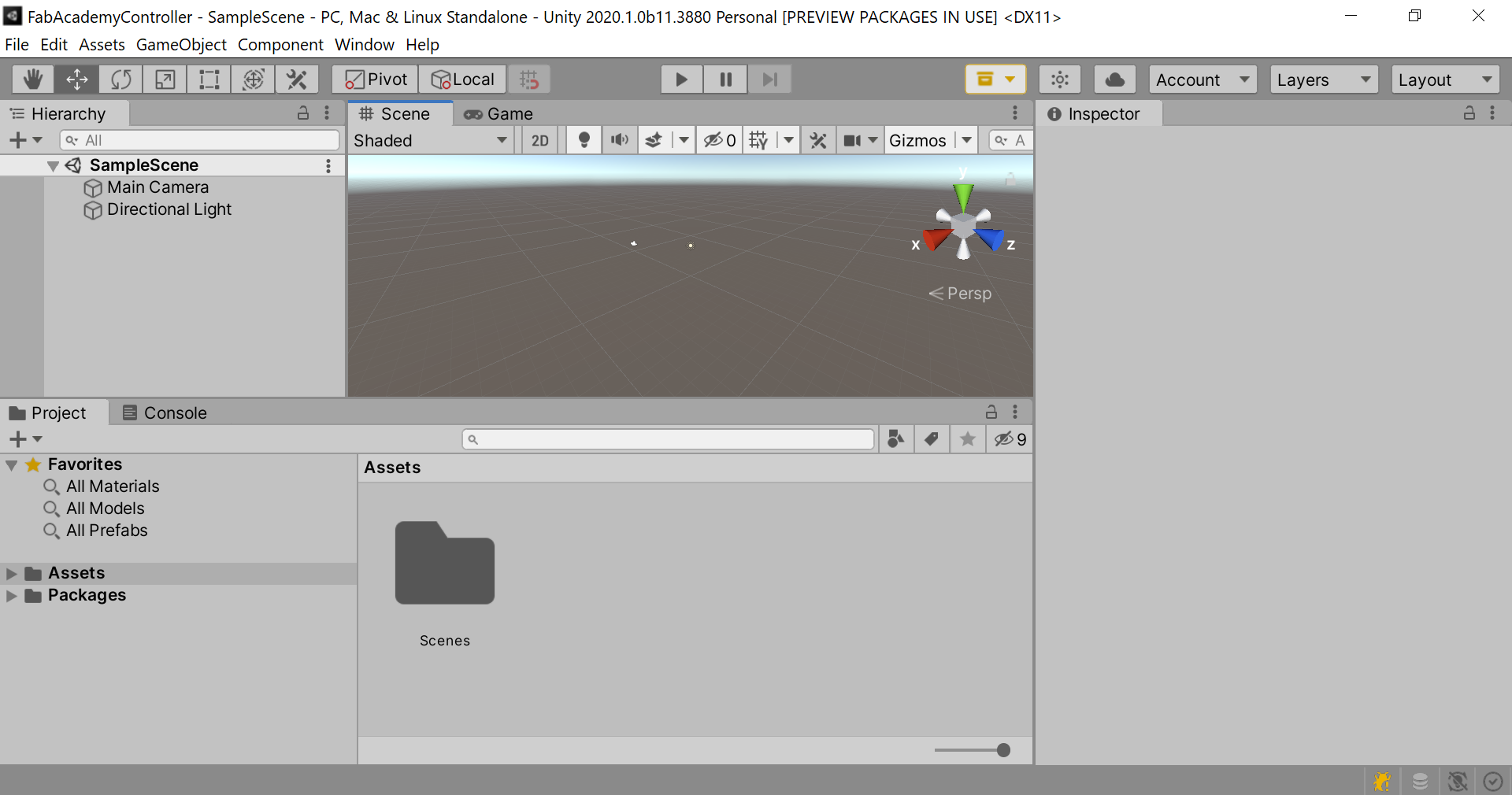
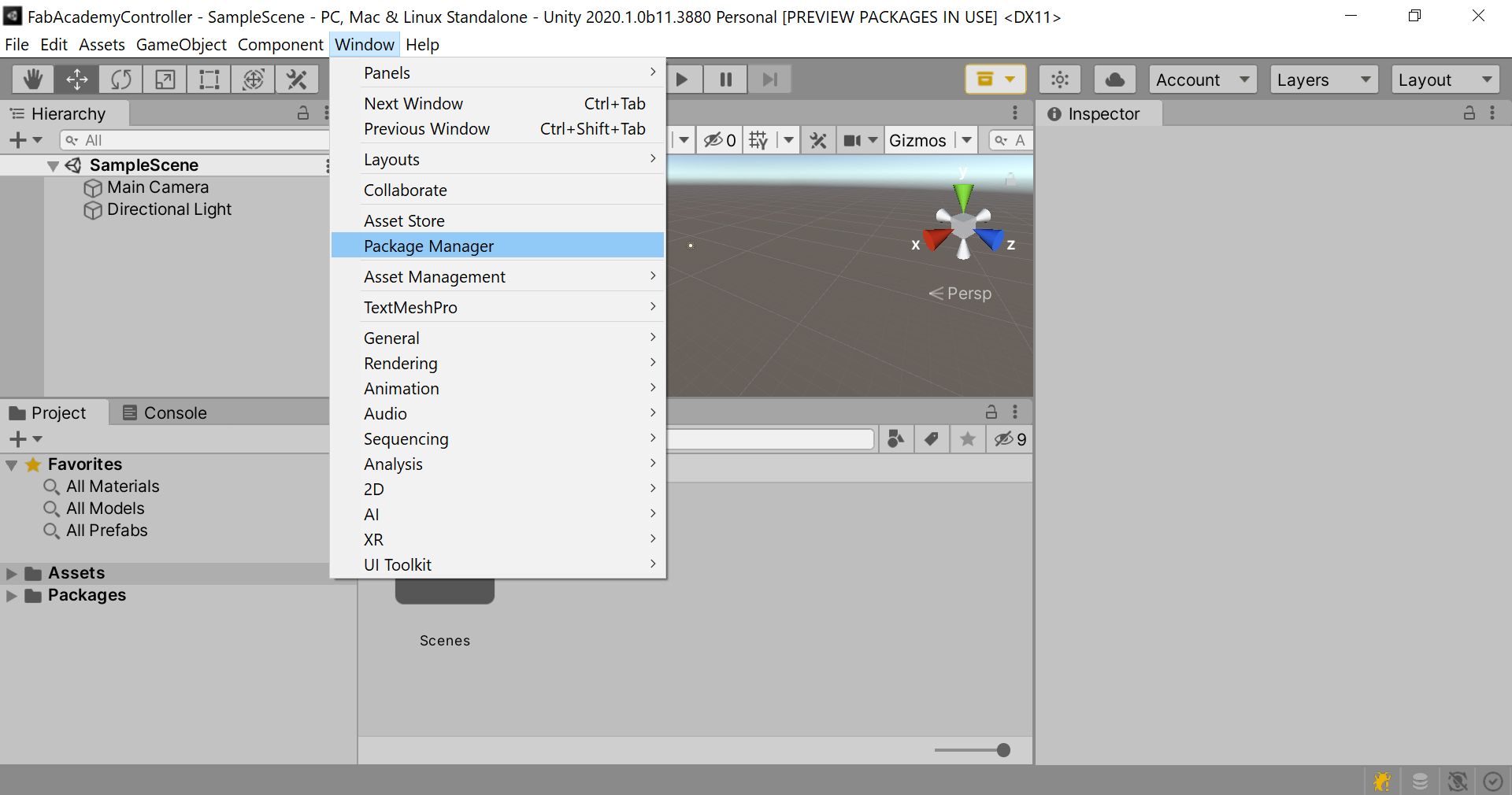
Window > Package Manager
-
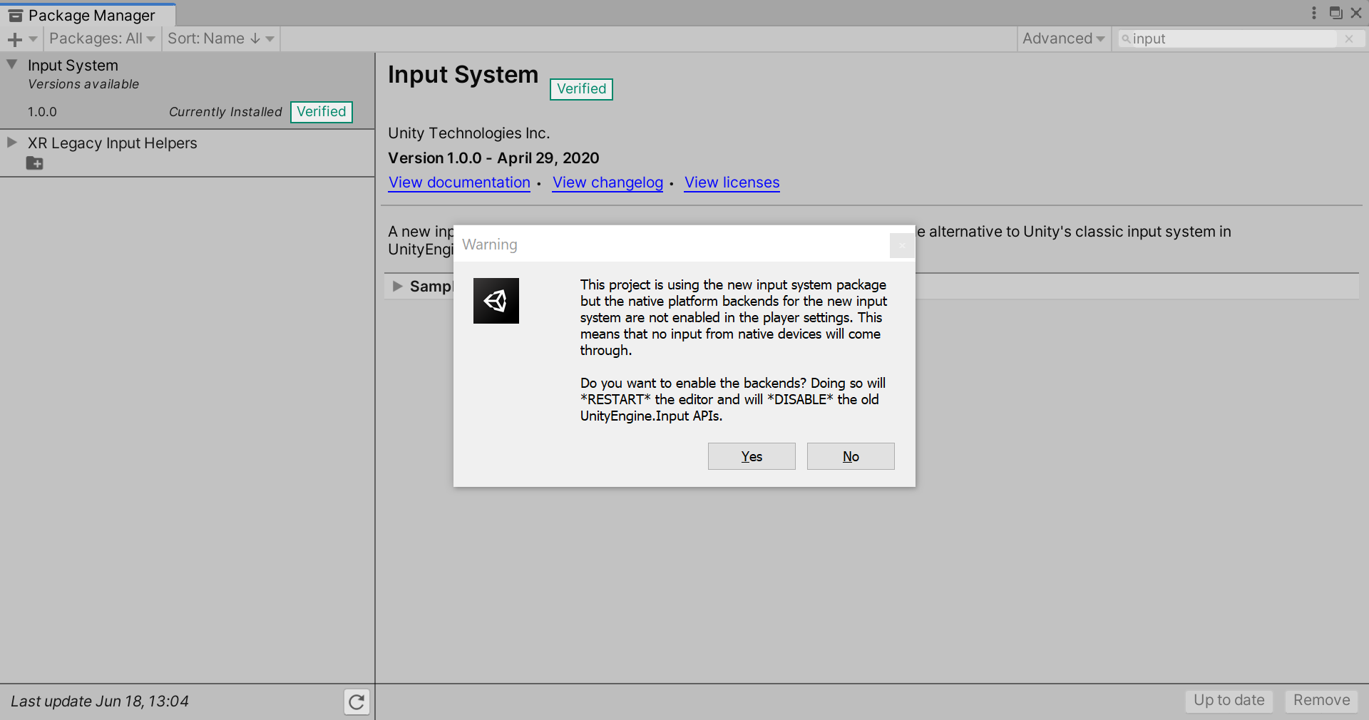
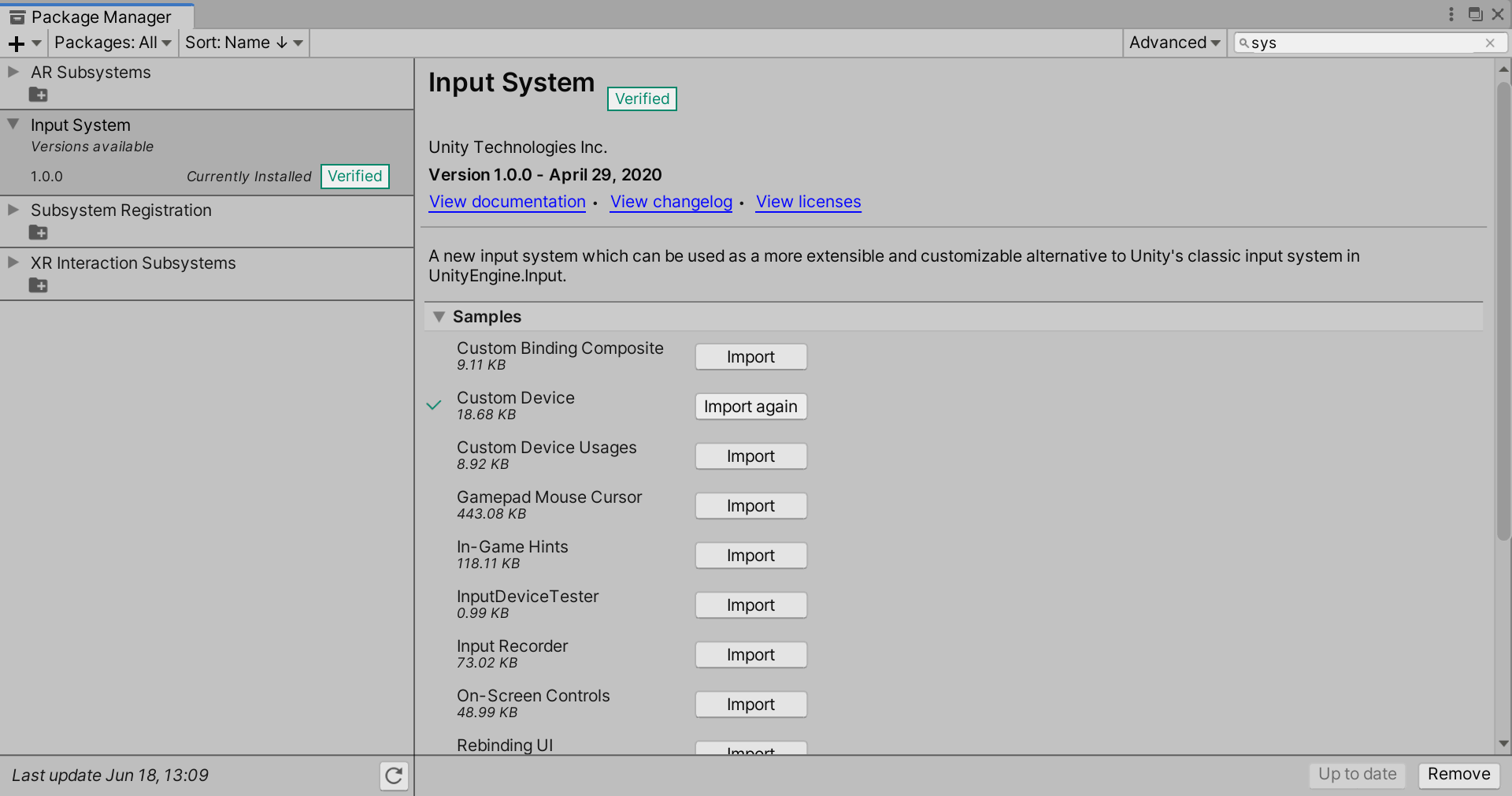
Make sure you show Packages: All
-
Search for Input System Package
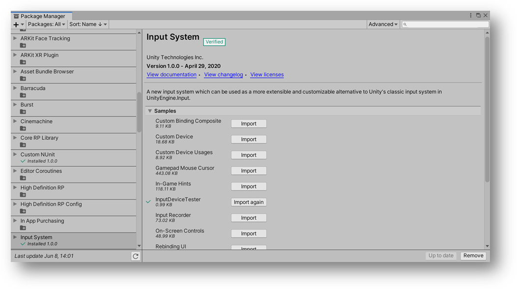
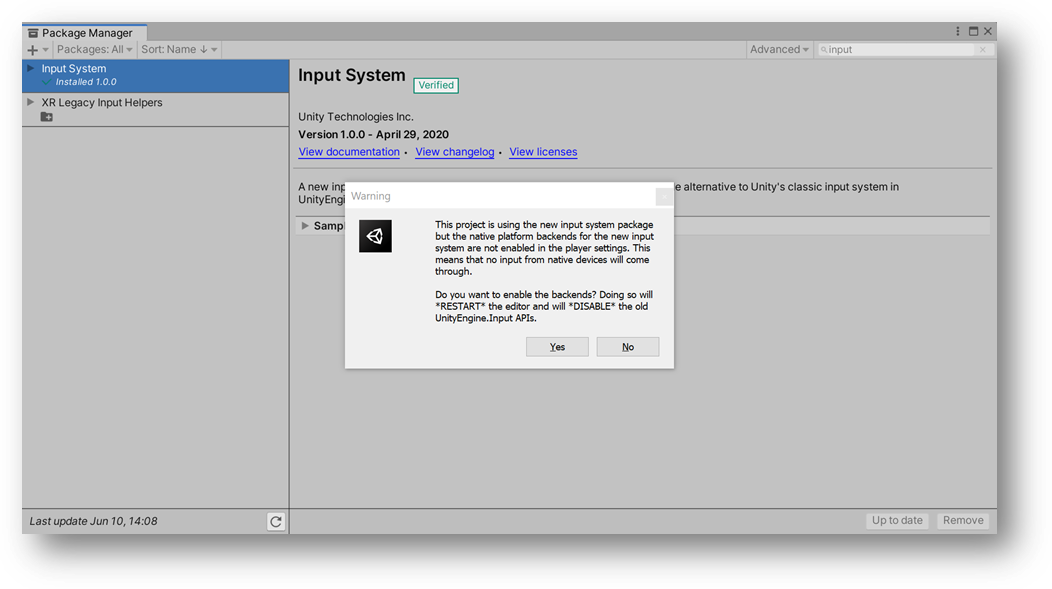
Follow the “Recomendded Settings”, by pressing “yes” after installing. Unity needs restarting after installing this package.
Tip
Use Unity Input Debbuger to view avaliable input devices.
To Access Input Debugger
Window > Analysis > Input Debugger
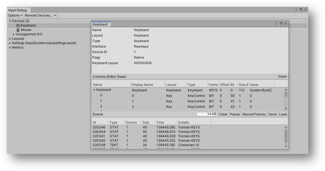
Controller is connected. In this case, the Device is Keyboard
Creating Inputs for Keyboard
Using Input Actions Assets
https://docs.unity3d.com/Packages/com.unity.inputsystem@1.0/manual/ActionAssets.html
- Under Project,
- Create an Input Actions
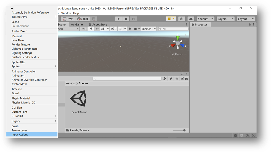
- Open the “New Controls” Input Actions
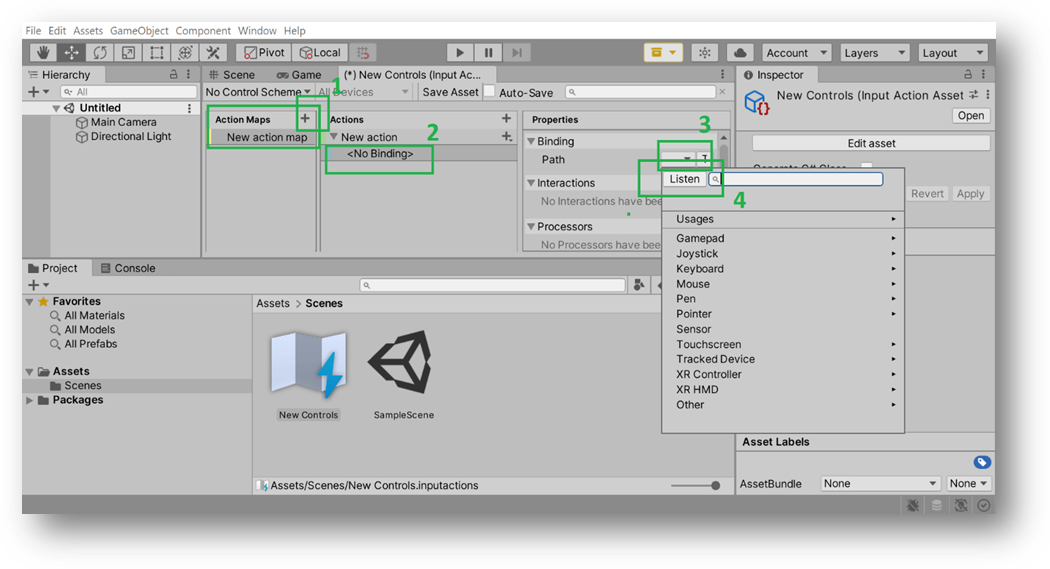
- Add an “Action Map” under Actions Maps.
A New action will be added by default.
Add a Binding to the Action.
Listen to add a Binding to New action.
Note
Since Controller is connected. In this case, the Device is Keyboard, a New action will be bound to a Keyboard button when pressed. Keyboard button “A” was pressed.
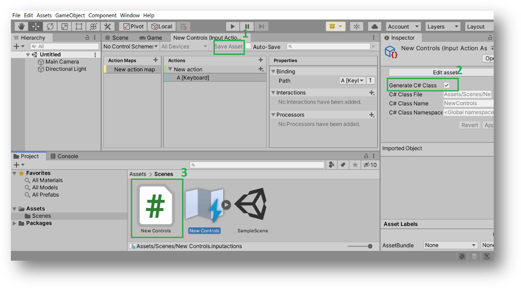
-
Save Asset and Generate C# Class
-
New Controls Scripts will be generated.
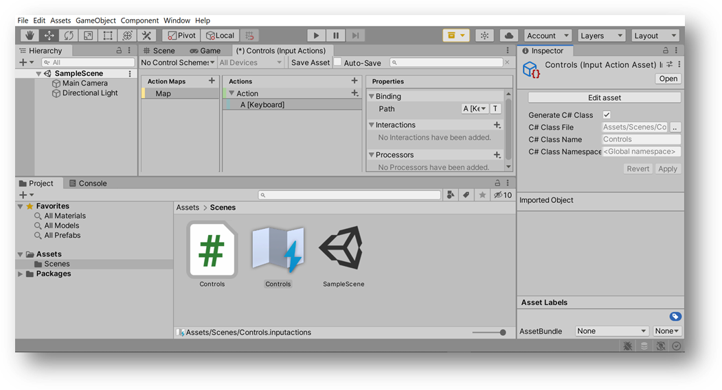
Warning
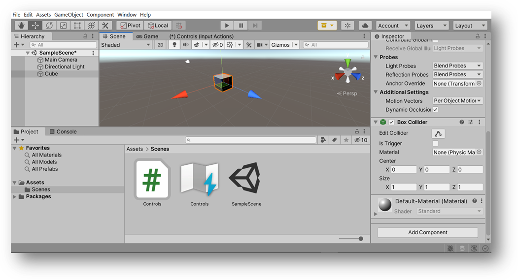
To make scripting easier later on, naming changes were applied: the following figure shows the naming of the created**Action Maps** as “Map”, the created Action as “Action” and the created Input Actions as “Controls”. The generated C# Class name is the same as the created Input Actions, which is “Controls”.
Creating the Simple Test Scene
Inputs from Keyboard will be used to interact with a Cube.
Add a new Cube to the Scene.
Right Click > 3D Object > Cube
Select the Cube, and Add Component that is a script.
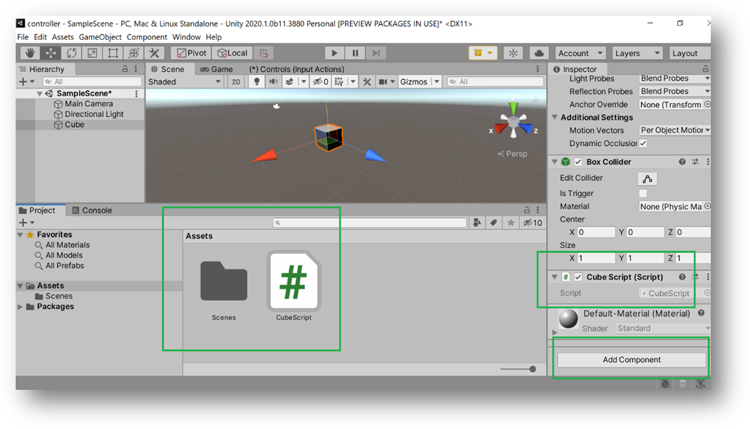
Cube Script was edited
using System.Collections;
using System.Collections.Generic;
using UnityEngine;
using UnityEngine.InputSystem;
public class Cube : MonoBehaviour
{
    // set controls equal to a new player controls object
    PlayerControls controls;
    void Awake()
    {
        //... created a player controls object to refer to
        controls = new PlayerControls();
        //following action map structure, access game play and then access the grow action
        //inside Grow function, transform dot local scale ... for the context, use lambda expression
        controls.GamePlay.Grow.performed += ctx => Grow();
    }
    //add a function to Grow that will be triggered when the action is performed
    void Grow()
    {
        transform.localScale *= 1.1f;
    }
    //make sure to enable and disable input actions whenever this object gets enabled or disabled
    private void OnEnable()
    {
        controls.GamePlay.Enable();
    }
    //make sure to enable and disable input actions whenever this object gets enabled or disabled
    private void OnDisable()
    {
        controls.GamePlay.Disable();
    }
}
Now … when the button is pressed, the cube gets bigger.
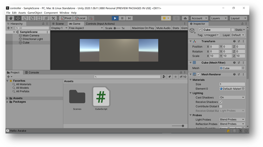
Unity-Keyboard-button-input.mp4
COMPONENT2, Test Game Scene: Cube interactions Using Arduino Input
Again, since a bottom-up approach was used and COMPONENT3 was experimented with at first, thus, it is time to add COMPONENT2: A Unity Input Device (that could be a fabricated board, but an Arduino was used for convenience and testing) was used to control a simple game scene (a Cube growing).
To get communication over COM ports with Unity to work, a library was used (later on modified for final project purposes). More about the Library
https://ardity.dwilches.com/
To connect board to Unity over a COM port, Ardity was modified to allow bidirectional communication over COM ports from Unity.
Ardity creates a thread in which it polls a COM port, all data it receives is stored in a shared thread-safe queue.
Later, your Unity program must either configure a callback, e.g. ReadSerialMessage() which de-queues the next message in queue. Additionally, SendSerialMessage() can be used to send data to the COM port.
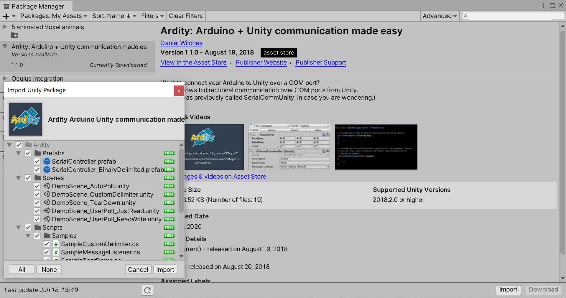
Installing and Configuring the Library
Download and Import Package
https://github.com/DWilches/Ardity/raw/master/UnityPackages/Ardity.unitypackage
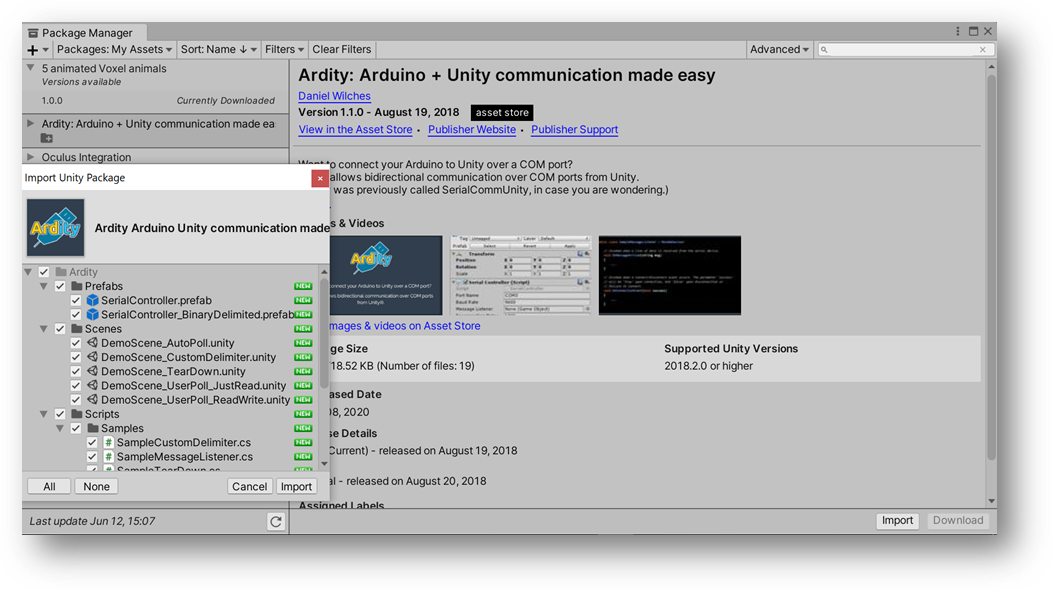
Sample Scene is available as a starting point
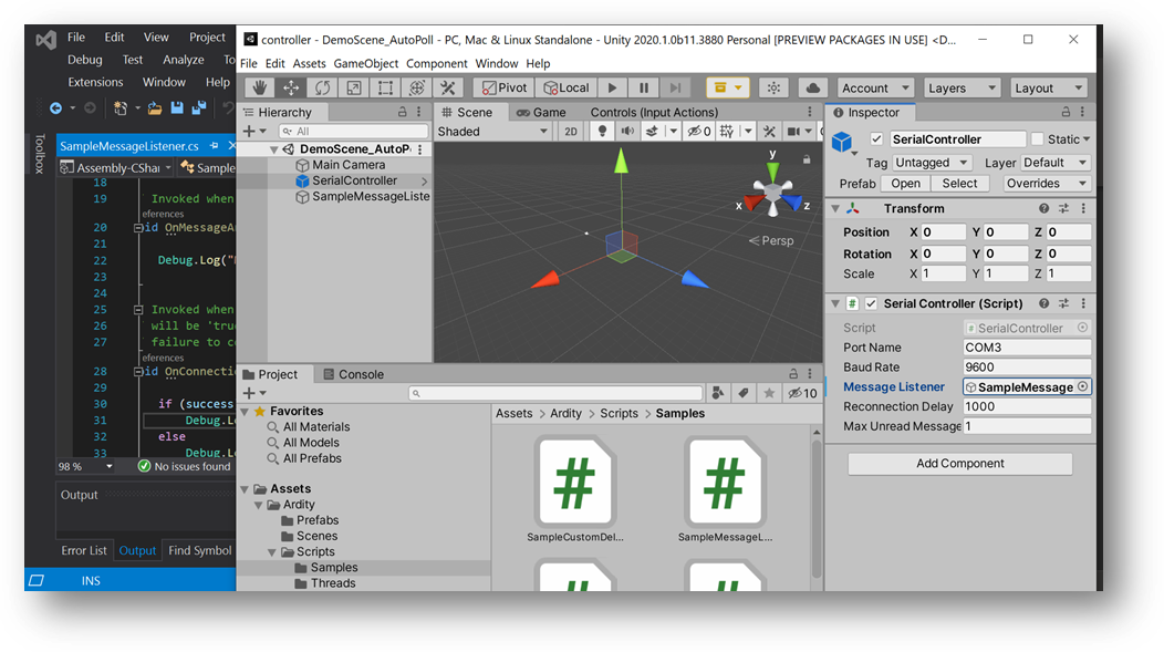
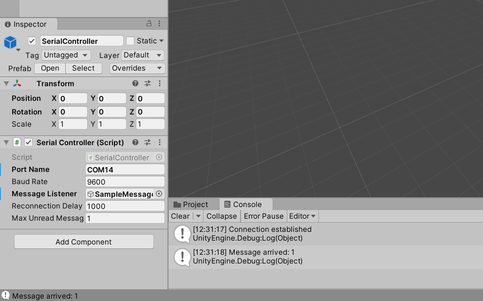
When configuring the Serial Controller Script (matching with the Arduino IDE), Debug messages will show under the Console tap in Unity. For documentation and debugging
https://github.com/dwilches/Ardity/blob/master/UnityProject/Ardity%20-%20Setup%20Guide.pdf
Message Using an Arduino
Now, instead of getting the Input from Keyboard directly, an Arduino Board was used as an Input. Note that the Arduino can be treated as a Keyboard.
An example tutorial:
https://www.arduino.cc/en/Tutorial/KeyboardMessage
Therefore, when the button connected to the Arduino is pressed, a text string is sent to the computer as keyboard input. An Arduino Due was used for testing.
https://www.arduino.cc/en/Guide/ArduinoDue
The following schematic was followed:
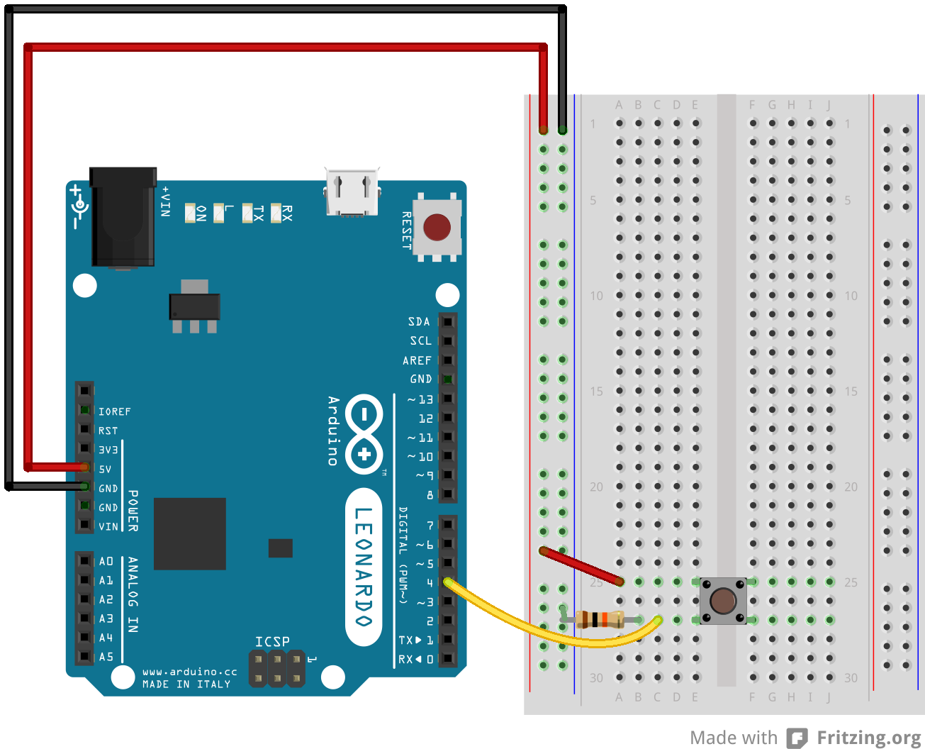
Note
Using the Native port enables you to use the Due as a client USB peripheral (acting as a mouse or a keyboard connected to the computer) or as a USB host device so that devices can be connected to the Due (like a mouse, keyboard, or an Android phone). This port can also be used as a virtual serial port using the “SerialUSB” object in the Arduino programming language.
Hence, either port in Due can be used for programming, but the native USB port allows for: 1) emulating a USB mouse or keyboard to an attached computer. To use these features, see the Mouse and Keyboard library reference pages 2) acting as a USB host for connected peripherals such as mice, keyboards, and smartphones. See the USBHost references. Thus, the Due cab be used to interface with USB devices or connect it to your computer and have it act like a USB device.
Tutorials > Built-In Examples > 02.Digital > Button
https://www.arduino.cc/en/tutorial/button
Modified code to Serial.println(“1”); and LED is used for debugging.
...
    if (buttonState == HIGH)
    {
      digitalWrite(ledPin, HIGH);
    }
    else
    {
      Serial.println("1");
      digitalWrite(ledPin, LOW);
    }
...
}
Connect the Arduino and Configure Serial Controller Script. Also, see Ardity - Setup Guide.pdf.
Run the Scene! When button is pressed, console will print the message.
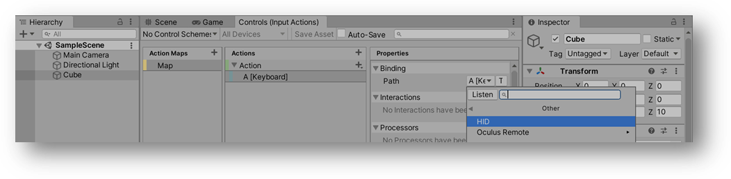
Edit the Binding to the Action to support the Arduino board, as an HID input.
Human Interface Device (HID) is a specification to describe peripheral user input devices connected to computers via USB or Bluetooth. HID is commonly used to implement devices such as gamepads, joysticks, or racing wheels.
For more information. See Unity Manual about HID, which explains the requirements for acting as a USB host device.
https://docs.unity3d.com/Packages/com.unity.inputsystem@1.0/manual/HID.html
The following images shows how HID input is supported in the Unity Input System.
When the button, connected to the Arduino is pressed, the cube gets bigger.
COMPONENT1, Unity Custom Device using a Fabricated Board
Now, instead of getting the Input from an Arduino Board, a FabAcademy Fabricated board will be used. See Input Board. The board can be connected to Joystick and used as Joystick, e.g., movement. See Joystick.
Arduino merely emulates the keyboard, not Custom Device Input and Board currently designed for Fab Academy cannot act/support a USB host device. Therefore, a different kind of Custom Device Input is needed. The following steps explain that. Additionally, the simple test cube scene is replaced with the actual game scene (made from scratch).
New Unity Project
Unity Package Manager
Install Input System from Unity Package Manager. Yes, to Restart.
Import Custom Device Sample! For integrating the fabricated board.
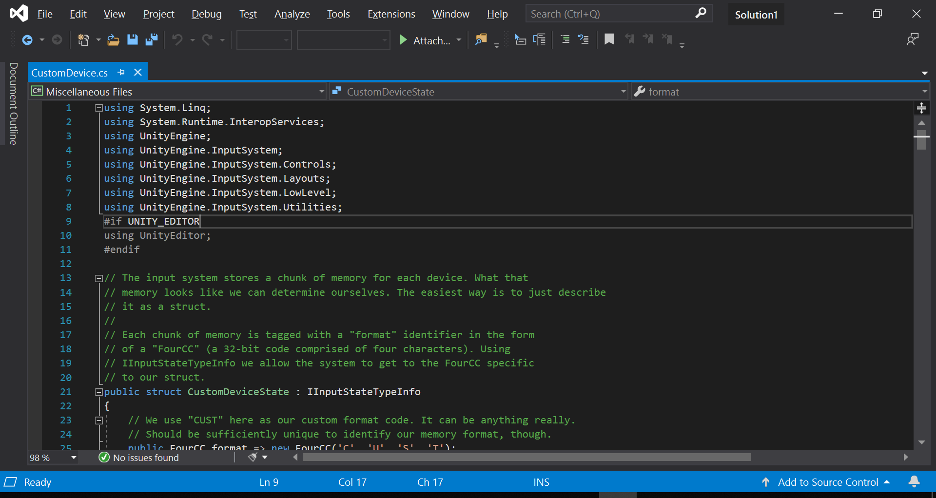
Edit Custom Device Script
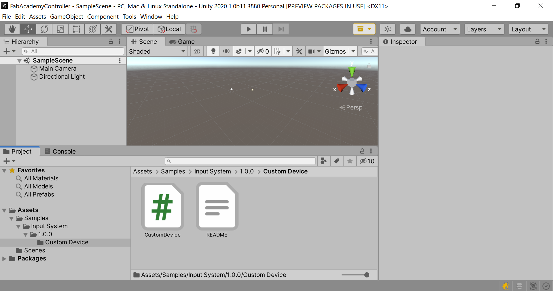
The sample code is well documented. Refer to script and comments CustomDevice.cs
Reference Documentation for Unity Input System 1.0
Struct FourCC
https://docs.unity3d.com/Packages/com.unity.inputsystem@1.0/api/UnityEngine.InputSystem.Utilities.FourCC.html
Controls
https://docs.unity3d.com/Packages/com.unity.inputsystem@1.0/manual/Controls.html
Devices
https://docs.unity3d.com/Packages/com.unity.inputsystem@1.0/manual/Devices.html
Assumptions Made, describing device inputs
- The device has a bitfield of buttons. Each bit indicates whether a certain button is pressed or not.
- A ushort field that contains the state of each possible button on the device can be constructed.
- The device also has a stick. The stick is stored as two unsigned bytes with the midpoint of each axis located at value 127.
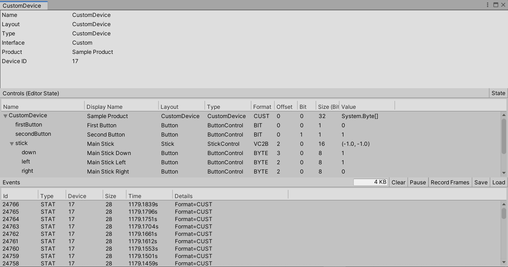
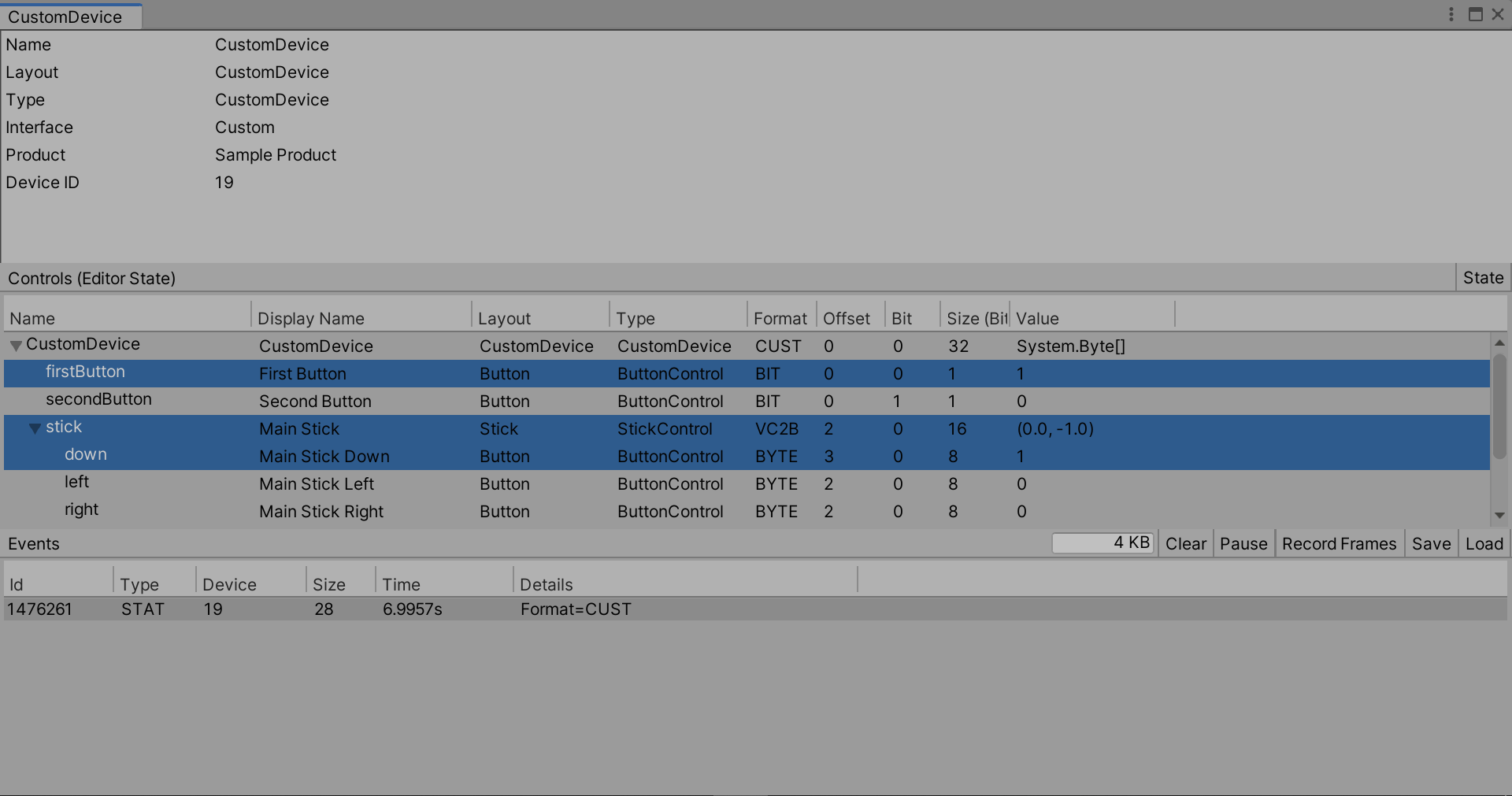
Create a Custom Device
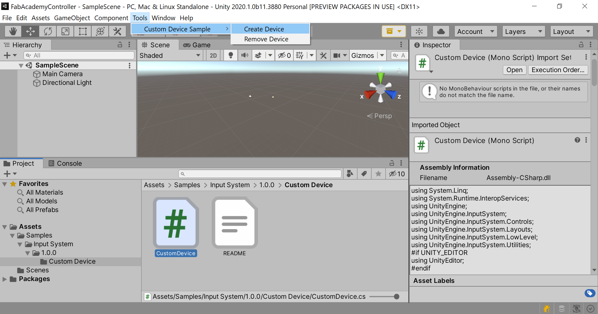
Device will show under the Input Debugger in Unity
From Script
When Buttons are pressed, the changes will show in the Debug menu (Observe change in Value)
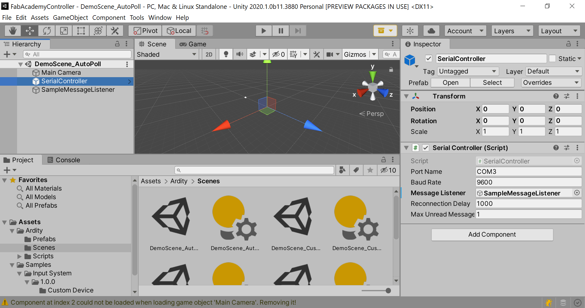
Communication over COM ports with Unity
The boards were connected to Unity over a COM port communication script, as in COMPONENT2.
Download and Import Package
https://github.com/DWilches/Ardity/raw/master/UnityPackages/Ardity.unitypackage
Sample Scene is available as a starting point
When configuring the Serial Controller Script (matching with the Arduino IDE), Debug messages will show under the Console tap in Unity.
Controller Message
Using the boards from Electronic Design Week.
Script, Modified
// Arduino pin numbers
const int SW_pin = 5; // digital pin connected to switch output
const int X_pin = 4; // analog pin connected to X output
const int Y_pin = 1; // analog pin connected to Y output
//const int Motor = 4; // analog pin connected to Y output

void setup() {
  pinMode(SW_pin, INPUT);
  digitalWrite(SW_pin, HIGH);
//  pinMode( Motor , OUTPUT);  // Must be a PWM pin
  Serial.begin(9600);
}

void loop() {
  if (digitalRead(SW_pin) == LOW)
  {
      Serial.println(digitalRead(SW_pin));
      //analogWrite( Motor , 153 );  // 60% duty cycle
      //delay(100);              // play for 0.1s
      //analogWrite( Motor , 0 );  // 60% duty cycle
  }
  else if (digitalRead(SW_pin) == HIGH)
  {
    Serial.println("Waiting...");
  }

  if (analogRead(X_pin) > 1000)
  {
    Serial.println("left");
  }
  else if (analogRead(X_pin) < 100)
  {
    Serial.println("right");
  }

  if (analogRead(Y_pin) > 1000)
  {
    Serial.println("up");
  } else if (analogRead(Y_pin) < 100)
  {
    Serial.println("down");
  }

  delay(100);
}
Note
A pull-up resistor was used in the Arduino code: a high state was needed as default (to match with the Unity implementation) and then changed to Low by the Unity Script Interaction. This can also be flipped, but modifications on Unity’s are also needed. Additionally, the numbers for defining the threshold are not arbitrary. Since the values coming from the Joystick are Analog and the input in Unity is defined to be Digital, couple values were experimented with till the threshold was found. A future implementation should define inputs as Analog on Unity’s Side.
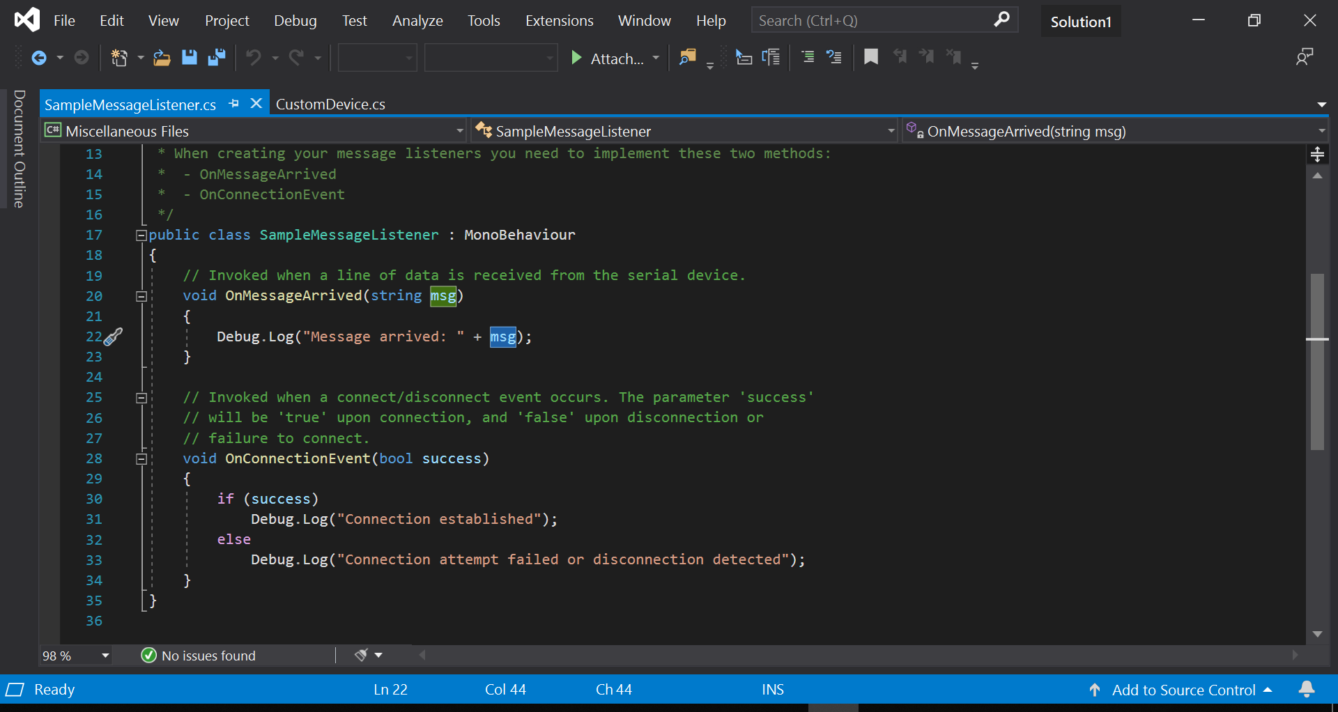
Connect the controller to PC using the FTDI cable. Then, modify the SampleMessageListner to work with CustomDevice.cs. The msg in the SampleMessageListner.cs Script is the packets sent from the board to the PC via the FTDI cable!
using UnityEngine;
using System.Collections;
using System;
using UnityEngine.InputSystem;

/**
 * When creating your message listeners you need to implement these two methods:
 *  - OnMessageArrived
 *  - OnConnectionEvent
 */
public class MessageListener : MonoBehaviour
{
    // Invoked when a line of data is received from the serial device.
    public void OnMessageArrived(string msg)
    {
        Debug.Log("Message arrived: " + msg);

        // this works with CustomDevice.cs it actually feeds input for the device. Notice
        // that we already have the IInputUpdateCallbackReceiver interface on CustomDevice class.
        // What this does is to add an OnMessageArrived method that will automatically be called
        // by the input system whenever it updates!
        // Here >> feed input to our devices.
        //
        // NOTE: InputSystem.QueueEvent can be called from anywhere, including from threads.
        //       So in this case, we have a background thread polling input from your device,
        //       that's where we can also queue its input events.
        //
        // The original script read input on CustomDevice class. It made up some stuff
        // there for the sake of demonstration. Additionally, It polled the keyboard...
        //
        // NOTE: The keyboard there was part of OnUpdate. however,
        //       they run OnUpdate from onBeforeUpdate, i.e. from where keyboard
        //       input has not yet been processed. This means that our input will always
        //       be one frame late. Plus, because we are polling the keyboard state here
        //       on a frame-to-frame basis, we may miss inputs on the keyboard.
        //
        // NOTE: One thing we could instead is to actually use OnScreenControls that
        //       represent the controls of our device and then use that to generate
        //       input from actual human interaction.

        var state = new CustomDeviceState();

        state.x = 127;
        state.y = 127;

        // WARNING: It may be tempting to simply store some state related to updates
        //          directly on the device. For example, let's say we want scale the
        //          vector from WASD to a certain length which can be adjusted with
        //          the scroll wheel of the mouse. It seems natural to just store the
        //          current strength as a private field on CustomDevice.
        //
        //          This will *NOT* work correctly. *All* input state must be stored
        //          under the domain of the input system. InputDevices themselves
        //          cannot private store their own separate state.
        //
        //          What you *can* do however, is simply add fields your state struct
        //          (CustomDeviceState in our case) that contain the state you want
        //          to keep. It is not necessary to expose these as InputControls if
        //          you don't want to.

        // Map buttons to 1, 2, and 3.
        if (msg == "0")
            state.buttons |= 1; // |= will only ever add bits to the target

        //string msg1 = msgSplit[1];
        // Map the stick.
        if (msg == "left")
            state.x -= 127;
        if (msg == "right")
            state.x += 127;
        if (msg == "up")
            state.y += 127;
        if (msg == "down")
            state.y -= 127;

        // Finally, queue the event.
        // NOTE: We are replacing the current device state wholesale here. An alternative
        //       would be to use QueueDeltaStateEvent to replace only select memory contents.
        InputSystem.QueueStateEvent(CustomDevice.current, state);
    }
    // Invoked when a connect/disconnect event occurs. The parameter 'success'
    // will be 'true' upon connection, and 'false' upon disconnection or
    // failure to connect.
    void OnConnectionEvent(bool success)
    {
        if (success)
            Debug.Log("Connection established");
        else
            Debug.Log("Connection attempt failed or disconnection detected");
    }
}
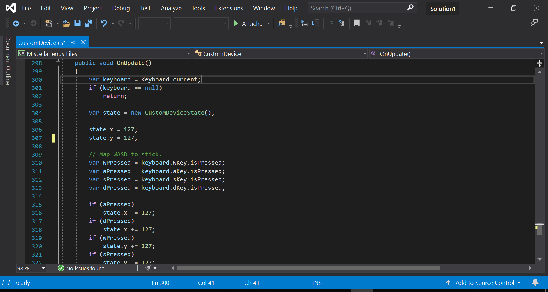
The original CustomDevice.cs read input on CustomDevice class. It made up some stuff there for the sake of demonstration. Additionally, it polled the keyboard. See image below.
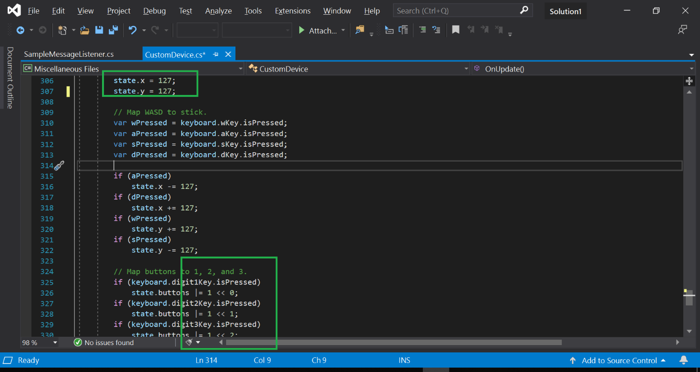
The keyboard there was part of OnUpdate. however, they run OnUpdate from onBeforeUpdate, i.e. from where keyboard input has not yet been processed. This means that our input will always be one frame late. Plus, because we are polling the keyboard state here on a frame-to-frame basis, we may miss inputs on the keyboard.
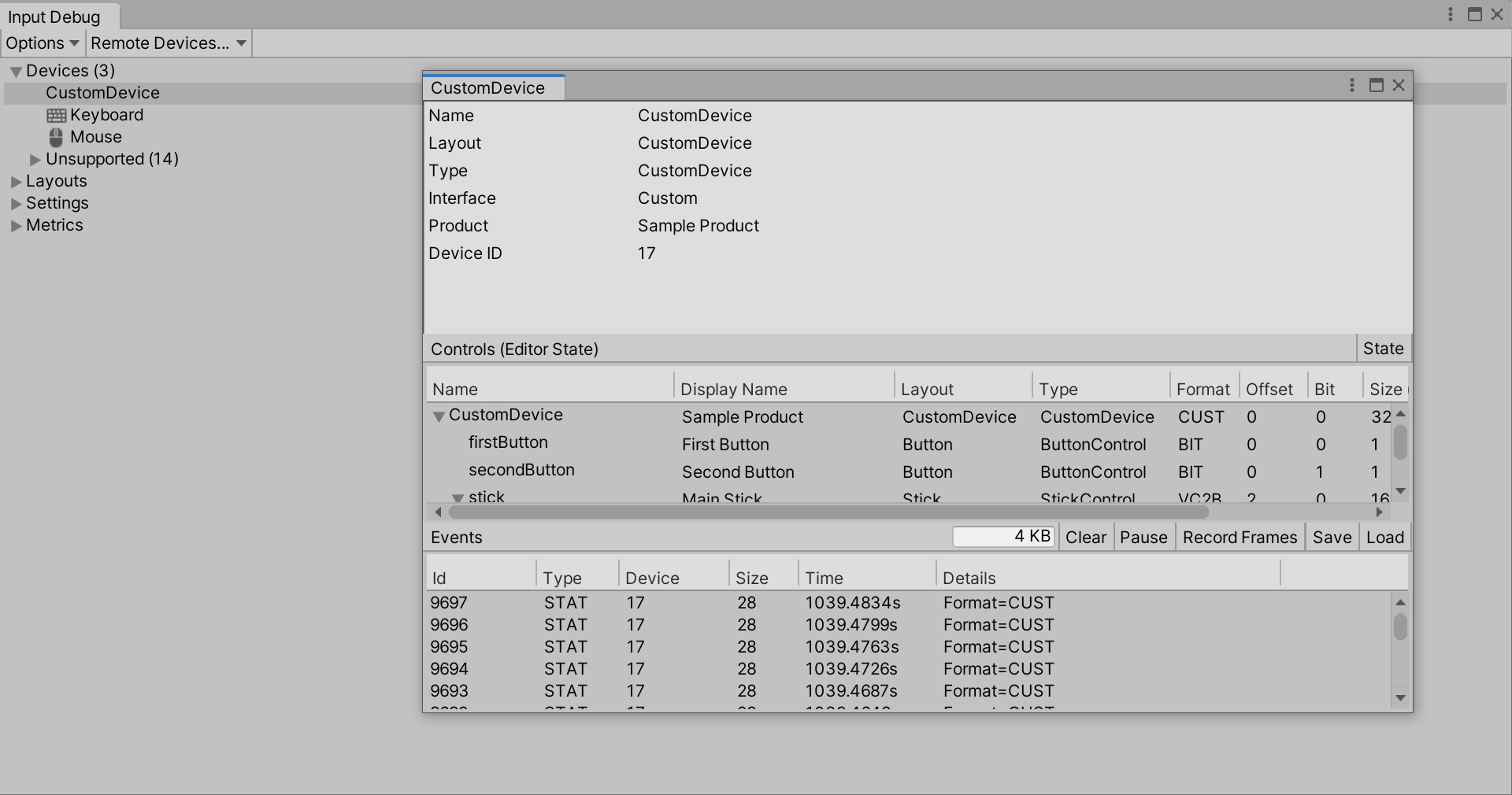
When the buttons/stick is pressed on the board, it will show on the CustomDevice in Unity.
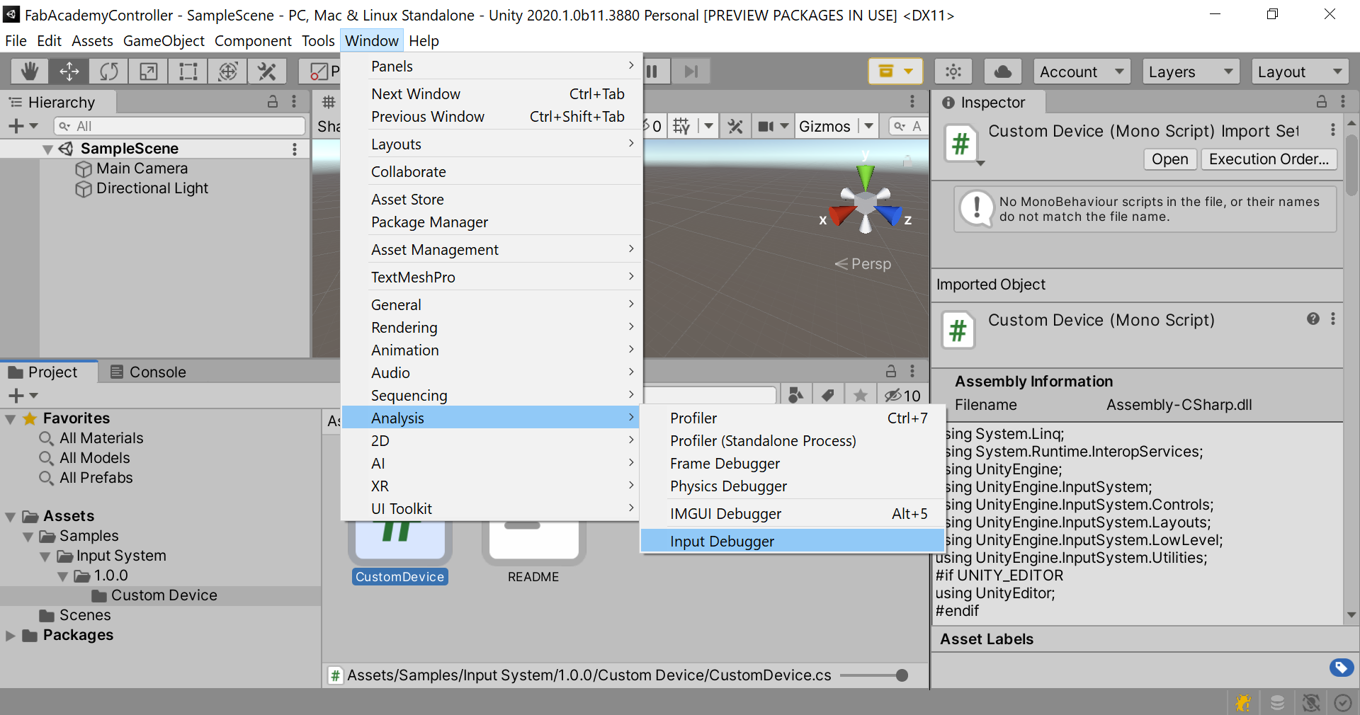
Tip
Use Unity Input Debbuger to view available input devices.
To Access Input Debugger
Window > Analysis > Input Debugger
Controller is connected. In this case, the Device is Custom Device. First Button was pressed along side the stick moving down.
Creating the Final Scene, with everything included
For this, the environment/scenes/scripts were not created, but modified an existing one. “Simple Demo” was imported.
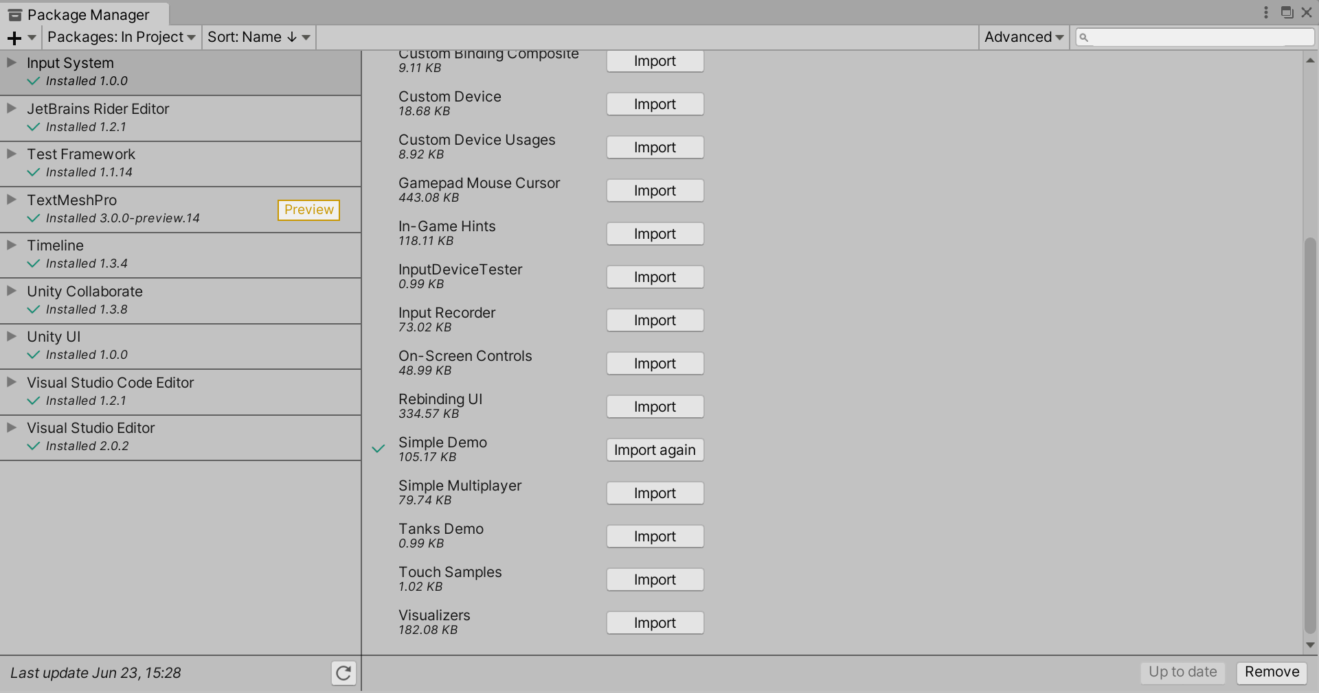
Below is the imported Simple Demo imported.
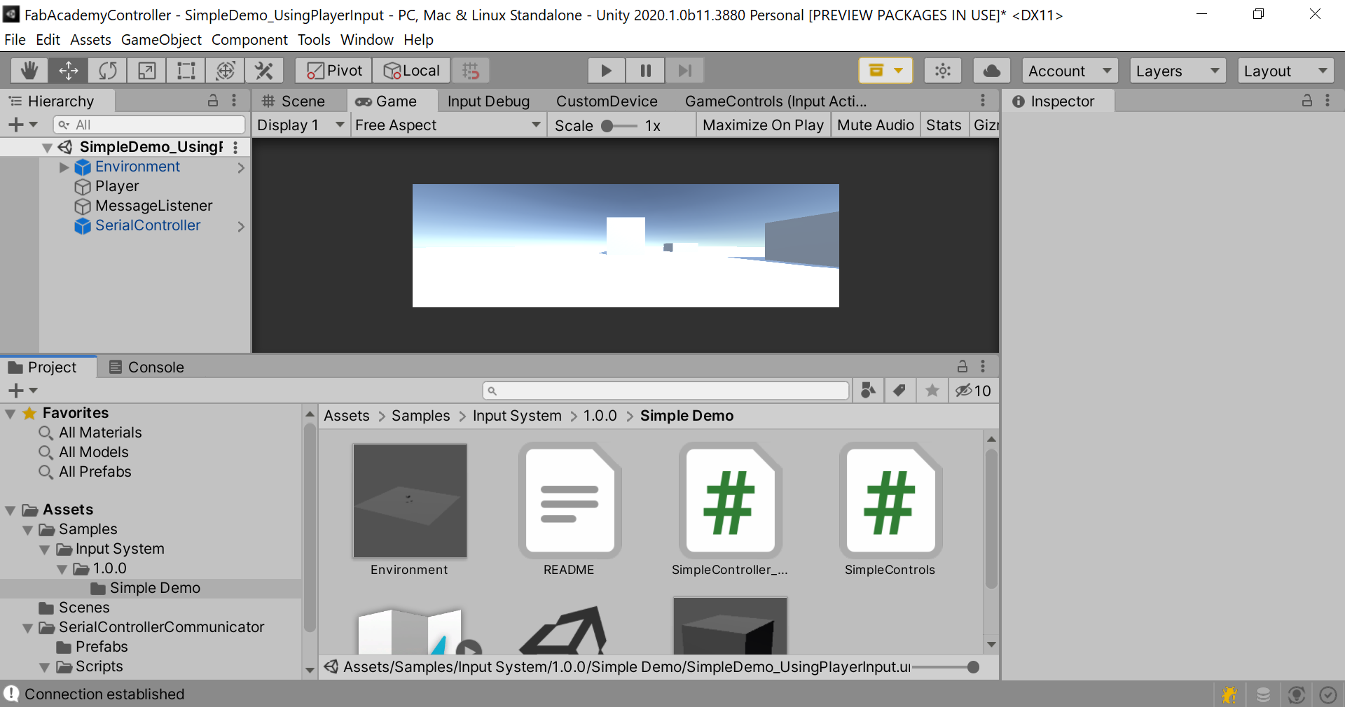
This sample shows how to set up a simple character controller using the input system. As there is more than one way to do it, the sample illustrates several ways, but only one was kept. Each demonstration is set up as a separate scene (all deleted except one). The basic functionality in all the scenes is the same.
You can move and look around and fire projectiles (colored cubes) into the scene. In the kept scenes, both custom controller and original bindings were supported (which is explained here).
SimpleDemo_UsingPlayerInput was kept and modified. (./SimpleController_UsingPlayerInput.cs)
This is the highest level of the input system. While scripting input like in the examples above can be quick and easy, it becomes hard to manage when there can be multiple devices and/or multiple players in the game. This is where “PlayerInput” comes in.
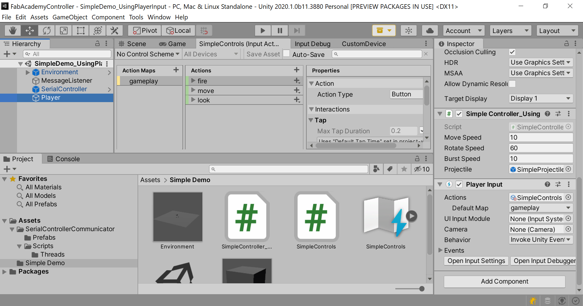
“PlayerInput” automatically manages per-player device assignments and can also automatically handle control scheme switching in single player (e.g. when the player switches between a Game Pad and mouse&keyboard).
In our case, we are not getting too much out of it since we don’t have control schemes or multiple players but still.
There are two script components on the “Player2 object, one being the usual “SimpleController” and the other being “PlayerInput”. “PlayerInput” refers to SimpleControls.inputactions (SimpleControls.inputactions).
It also has “gameplay” set as the “Default Action Map” so that the gameplay actions will get enabled right away when “PlayerInput” itself is enabled.
For getting callbacks, we have chosen “Invoke Unity Events” as the “Behavior”.
“Events” foldout in the inspector, show that “OnFire”, “OnMove”, and “OnLook” are added to the respective events. Each callback method here looks like the “started”, “performed”, and “canceled” callbacks.
“MessageListener” and “SerialController” were added to get input from the designed custom controller hardware.
Note
Hierarchy was changed. Some scripts were renamed. Ardity was removed and only certain scripts were kept from that library. Some code was refactored just to keep everything neat and organized!
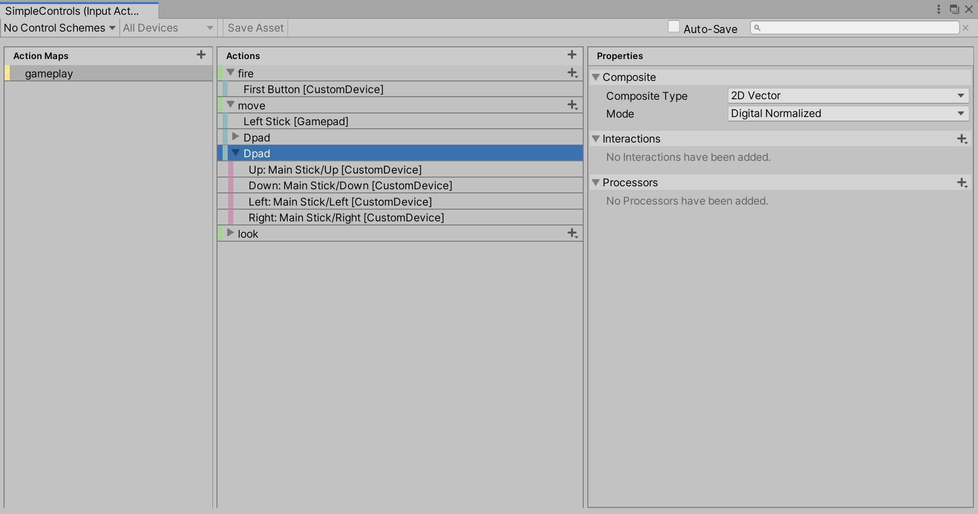
Add a Binding to the Actions. Joystick Button shows as First Button.
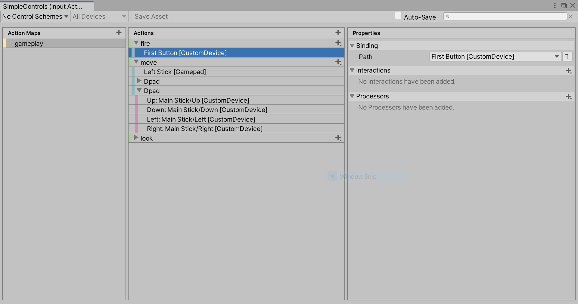
Add a Binding to the Actions. Joystick’s move shows as Dpad.
The following video shows everything working together!
Conclusion and Challenges
The Input manager is new to Unity, and the current version did not exist before Unity2020. It was a hassle to get it to work since there were not examples out there, apart from Unity’s official documentation.
Also, it was tricky getting many components to work together. However, it can be explained as the following: the Plugin can be boiled down to the The SampleMessageListener, which picks up Serial.println(“”) messages sent by the board (when configured). Within SampleMessageListener script, there is OnMessageArrived(string msg) method, which updates the CustomDeviceState() –within the same method.
The experimental bottom-up approach and dividing the work into components actually helped getting this to work. Starting small, with a Keyboard/Arduino has helped in understanding and envisioning how the whole thing would work.
Moreover, there has been a lot of tweaks here and there … and some code refactoring, all final scripts/configurations can be found under files.
This has been a fun assignment, and probably the most crucial for completing the final project later on.
Group Assignment
Tkinter, Blynk for Python and Processing.
Tkinter
Tkinter is a popular programming package for graphical user interface or desktop apps. The Button control also called widgets are used to display buttons in developed application while the Canvas widget is used to draw shapes (lines, ovals, polygon…) in your application.
https://docs.python.org/3/library/tkinter.html
-
It provides diverse widgets, such as labels, buttons, and text boxes used in a graphical user interface application.
-
Tkinter is an open source and it is available under the Python License.
Hello World Demo interface was made
Blynk
Blynk is a mobile application that allows users to build convenient interfaces to control hardware from smartphones.
The benefits of Blynk includes:
-
User-friendly interface: The interface of Blynk itself is well-designed. Adding widgets or changing the layout is intuitive.
-
Convenient operation: Users can easily add widgets to the interface for controlling the hardware. The way to modify the properties of the widgets is also simple, mostly by defining the pins and value range.
-
Easy connection with hardware: Blynk can connect to hardware via Ethernet, Wi-Fi, Bluetooth, Cellular, and Serial.
-
High compatibility with different devices: This application is available to both IOS and Android users. On the other hand, the virtual ports allow users to presumably connect to any kind of hardware without worrying about the ports.
On the other hand, the drawbacks of Blynk are:
-
Limited adjustable features: From the aesthetic design point of view, users have limited options in customizing the interface, mostly just the size and position of the widget. Users do not have much choice regarding styling the interface.
-
Limited available options for free users: Adding widgets to the interface cost “Energy”. Adding simple components like slider bars and buttons can cost all the free energy of users. For any additional features, users need to purchase extra energy
Blynk was used durning a Demo application for implemting a slider for controlling a motor

#define BLYNK_PRINT Serial
#include <ESP8266WiFi.h>
#include <BlynkSimpleEsp8266.h>
#include <Servo.h>

Servo servo;

char auth[] = [Blynk Auth Token];
char ssid[] = [Your Wi-Fi ssid];
char pass[] = [Your Wi-Fi password];
void setup()
{
    Serial.begin(9600);
    Blynk.begin(auth, ssid, pass);
    servo.attach(2); // NodeMCU D8 pin
}
void loop()
{
    Blynk.run();
}

BLYNK_WRITE(V1)

{
    servo.write(param.asInt());
}
BLYNK_WRITE(V2)
{
    servo.write(45);
} BLYNK_WRITE(V3)
{
    servo.write(90);
} BLYNK_WRITE(V4)
{
    servo.write(135);
}
Processing
Processing is a flexible software sketchbook and a language for learning how to code within the context of the visual arts. Since 2001, Processing has promoted software literacy within the visual arts and visual literacy within technology. There are tens of thousands of students, artists, designers, researchers, and hobbyists who use Processing for learning and prototyping.
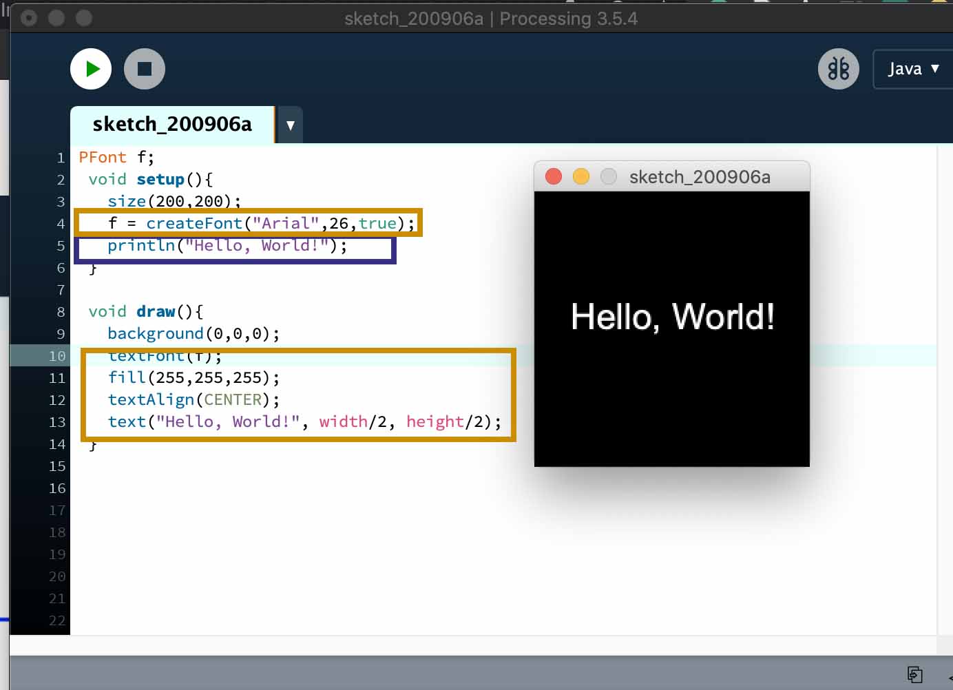
In this example we show how to print “Hello world!” in the console (used for testing purposes, e.g. error-messages) and how to print it on a window. Window is created with size(x,y) and it’s background is set as (0,0,0)(black).
Marked with blue squares on picture above is two ways to print on text on the console. Less useful way to print it is to put it under the Setup-section of the code. This will print it only once when the software is launched. Another way is to put it under the Draw-section. This will print it in every loop. Useful case would be inside an if-sentence to see that the code actually works properly.
Marked with orange squares on the picture above is the way to print “Hello world!” on the window. This took few more lines compared to printing only on the console. First declaring Font and then creating the font. The draw()-section specifies which font is used, it’s fill color, text aligning and finally calling the text()-function. Text has 3 arguments which are displayed text, X- and Y-coordinate. In this case, width/2 and height/2 to center it near middle were used.
PFont f;
 void setup(){
   size(200,200);
   f = createFont("Arial",26,true);
   println("Hello, World!");
 }
 void draw(){
   background(0,0,0);
   textFont(f);
   fill(255,255,255);
   textAlign(CENTER);
   text("Hello, World!", width/2, height/2);
 }
Files
- Arduino Scripts.
- Unity Scripts 01 and Unity Scripts02. Includes scripts and artefacts (no config, user settings or meta). For full code (more than 100mb), see github.com/ybarhoush/FabAcademy2020Project.
For full code (more than 100mb), see