8. Computer Controlled Machining
-
Individual Assignment
- Make something big!
- Design
- Mill
- Assemble
- Make something big!
-
Group Assignment
- Test runout, alignment, speeds, feeds, and tool-paths for machine
Individual Assignment
Simple Shelf Design using Fusion360.
Design
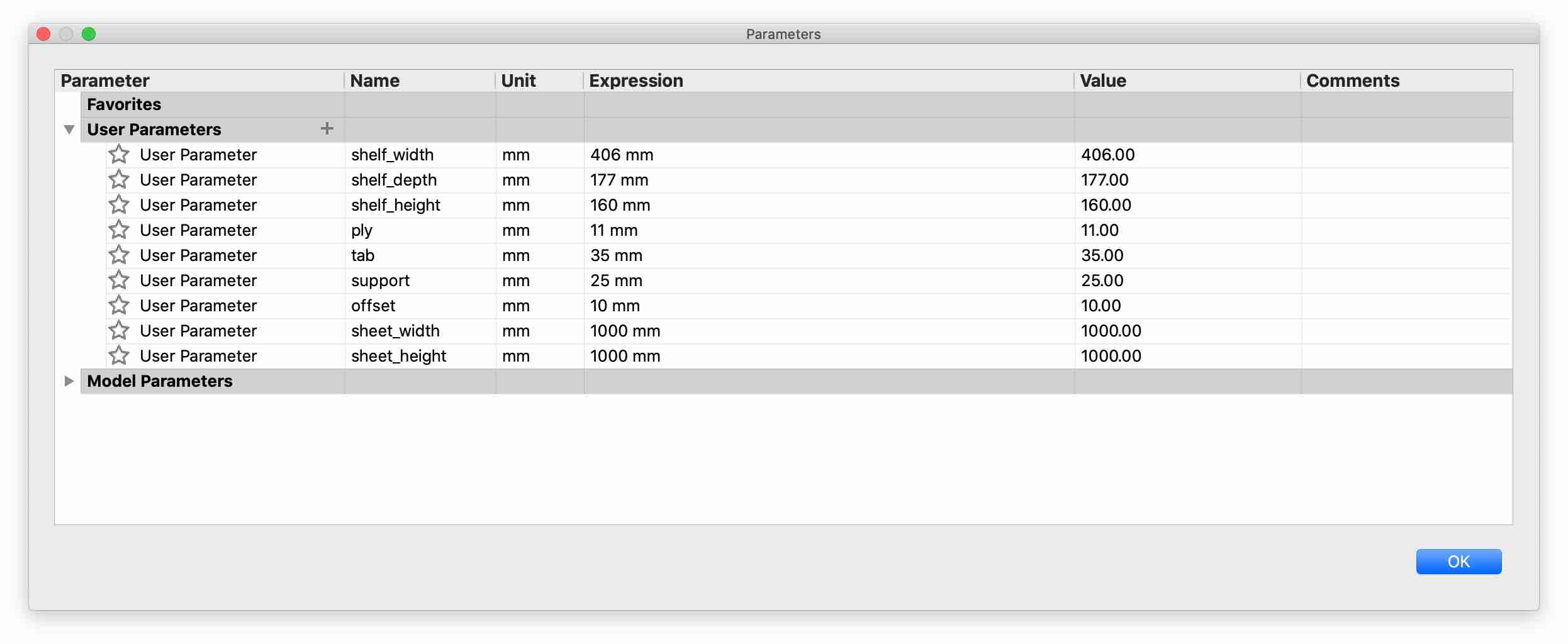
- Create Parameters
It allows for parametric modelling where modifications at anytime and reflected everywhere in the design.
Modify > Change parameters
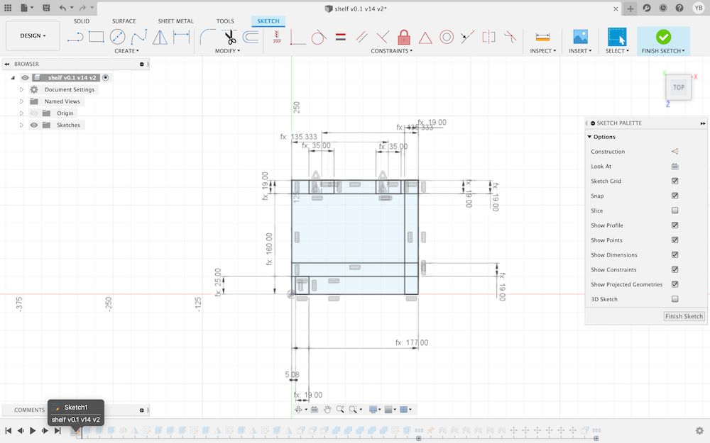
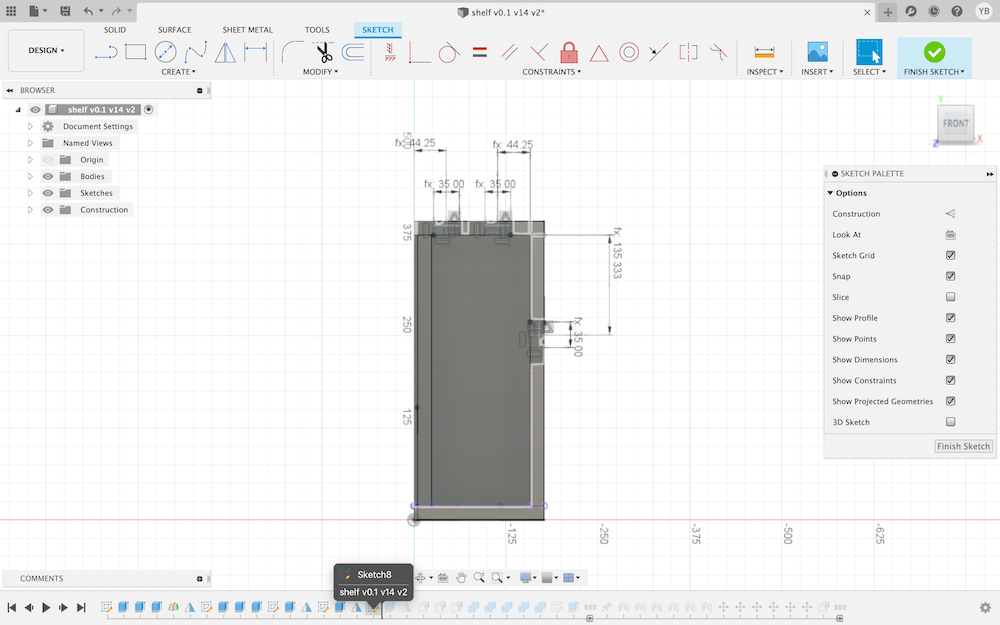
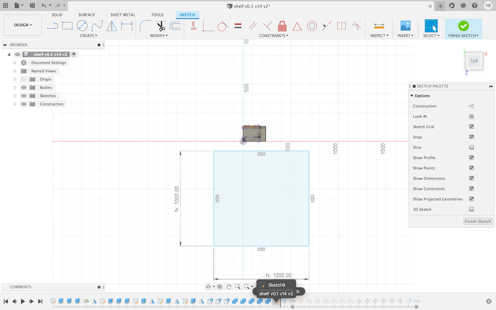
- Create 1st Side (Sketch)
Sketch > Create Sketch
This will be one of the sides for the shelf, a starting point. Draw rectangles and annotate the different parameters: e.g., depth, width and material thickness. Finnish Sketch when done.
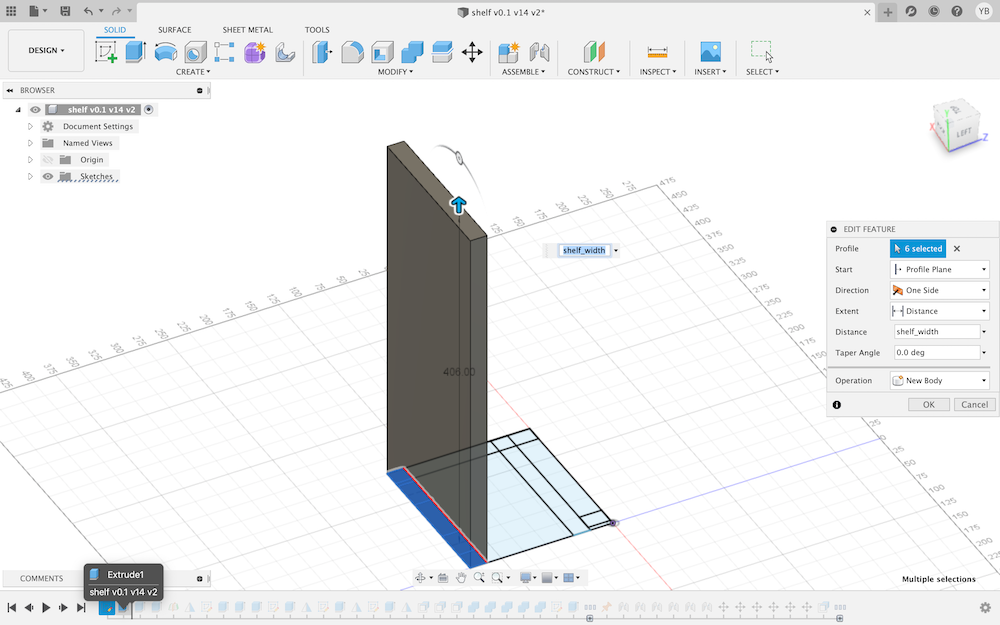
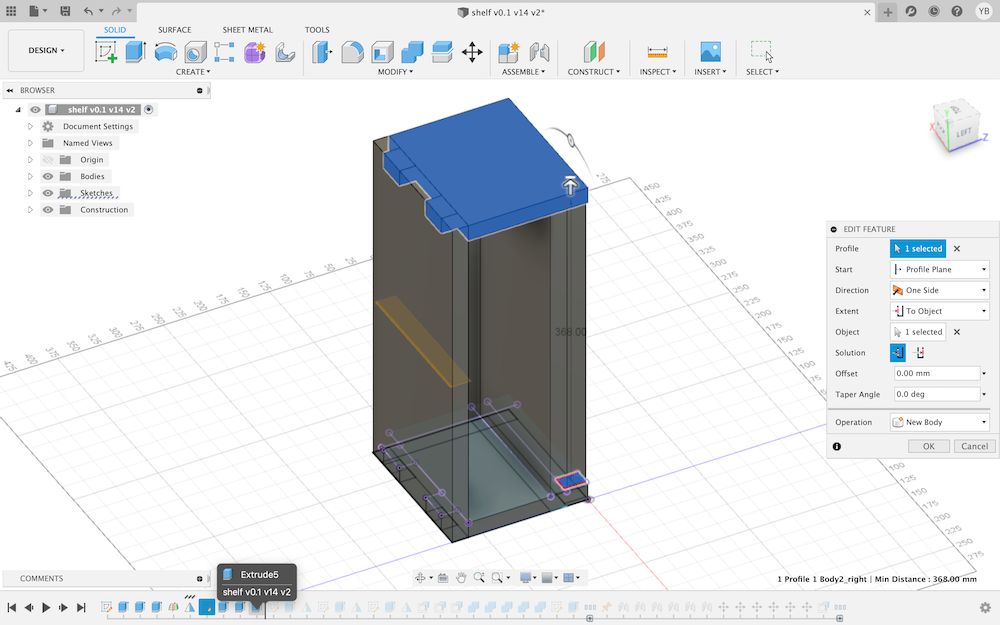
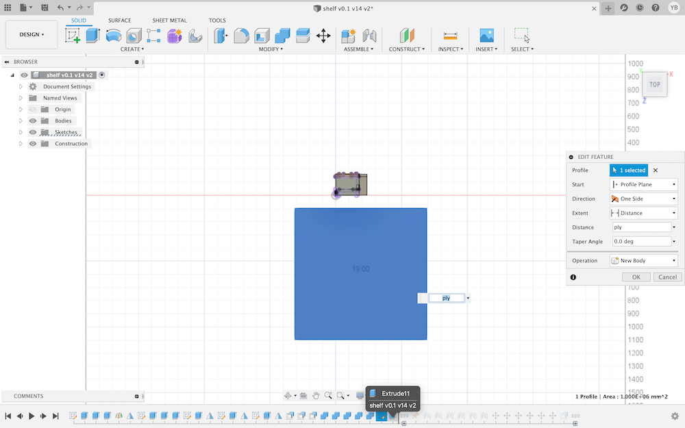
- Create Top Side (Extrusion)
Create > Extrude
This allows for extruding the sketch. Select the rectangle drawn and extrude to the defined parametric width. This will be the top of the shelf.
Note
Make sure that all extrusions, for making the sides, are new bodies
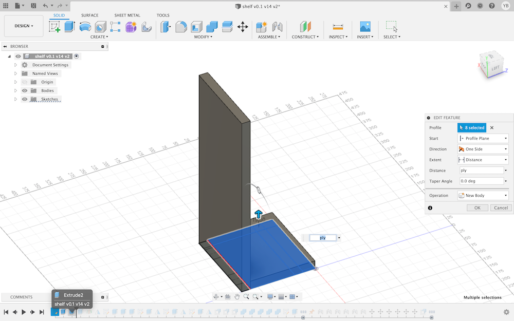
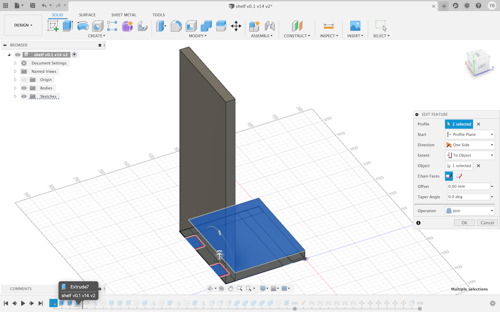
- Create 1st Side (Extrusion)
Do the same rest to the same of the sketch, and extrude it to the defined parametric material thickness. This will be one of the sides of the shelf.
- Create Tabs for 1st Side
Note
make sure that all extrusions for tabs are joint bodies
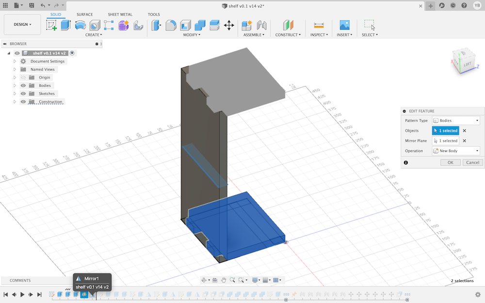
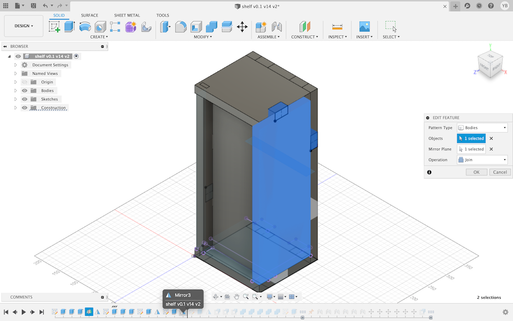
- Create 2nd Side (Mirror the 1st Side)
It will be easier to create the other side, with mirroring than sketching. For mirroring, a plane is required.
Construct > Mid-plane
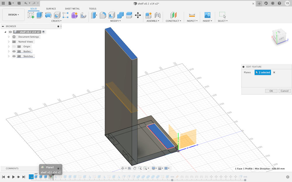
Select the side, which is the Body that needs to be mirrored.
Create > Mirror
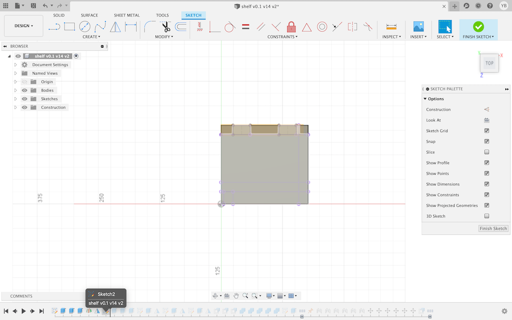
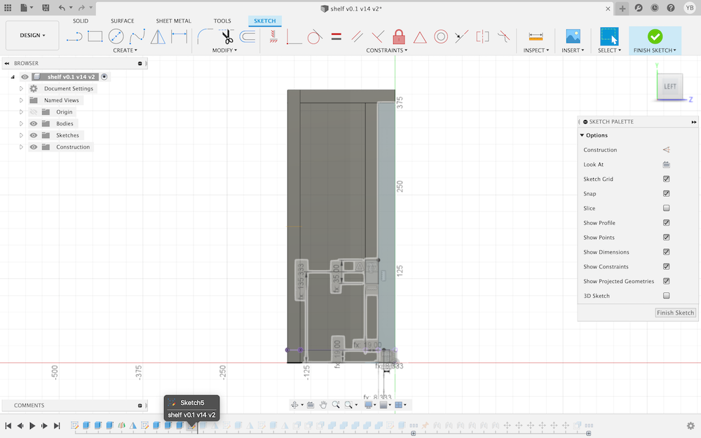
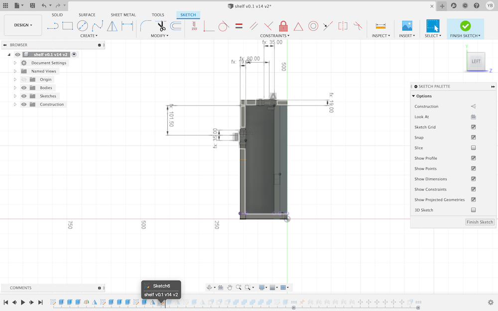
- Create Projected Sketch (Interior)
To work on the inside, without having to make a sketch from scratch, a Projected Sketch can be used.
    Sketch > Create Sketch
    Sketch > Project Include > Project
Select the lines of the outer sketch. Then, Finnish Sketch.
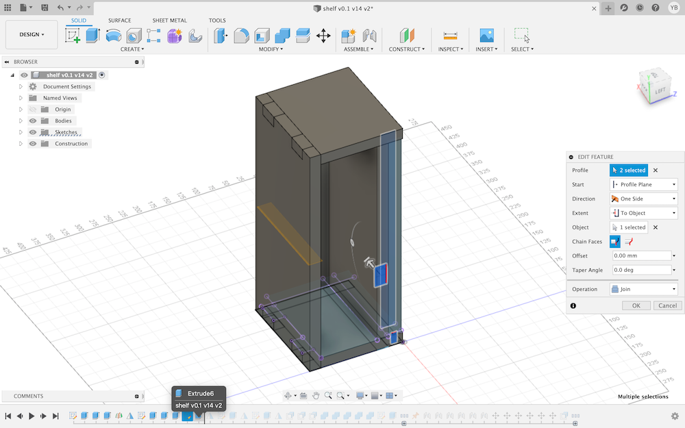
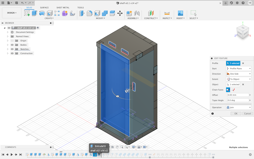
- Create the Back Side of the shelf
Create > Extrude
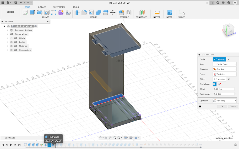
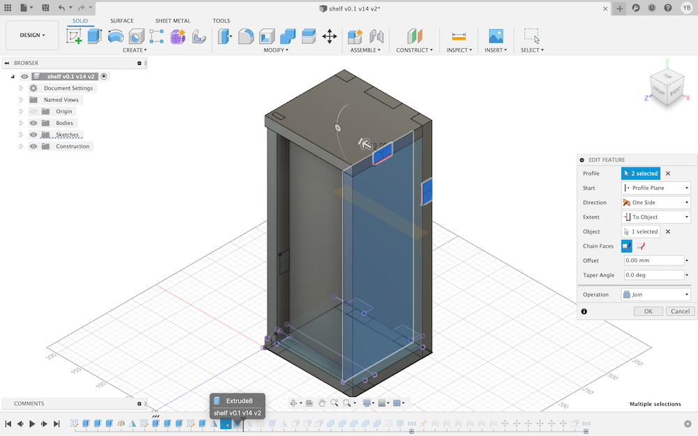
- Create the Bottom Side fo the Shelf
Create > Extrude
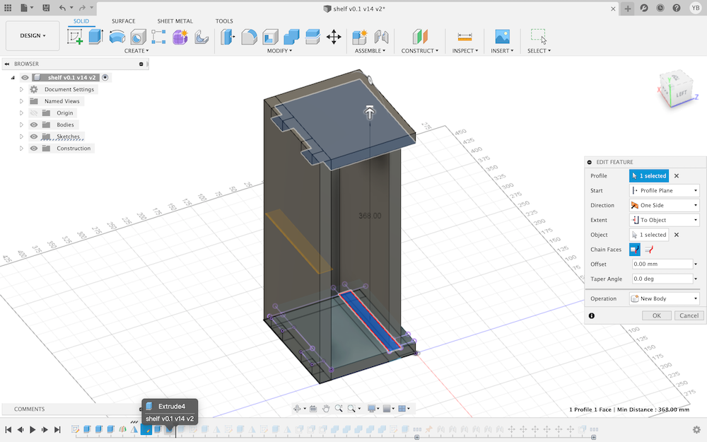
- Create the Bottom Support
Create > Extrude
- Create Tabs (Sketch), on the bottom support
- Create Tabs (Extrusions), on the bottom support
Create > Extrude
- Mirror the Tabs for the bottom support
Create > Mirror
- Create Tabs (Sketch), for the Back Side of the Shelf
- Create Tabs (Extrusions), for the Back Side of the Shelf
Create > Extrude
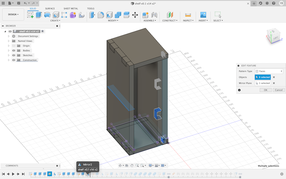
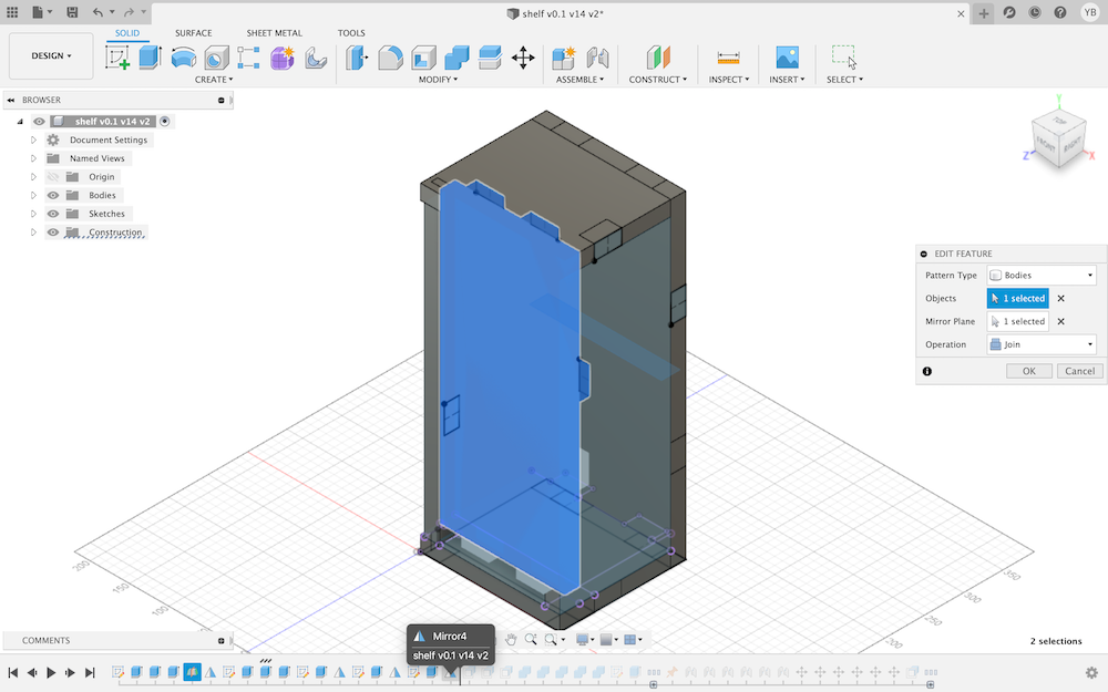
- Mirror the Tabs for the Back Side of the Shelf
Create > Mirror
- Create Tabs (Sketch), for the Back Side of the Shelf
- Create Tabs (Extrusions), for the Back Side of the Shelf
Create > Extrude
- Mirror the Tabs for the Back Side of the Shelf
Create > Mirror
- Add a Lip to the Side
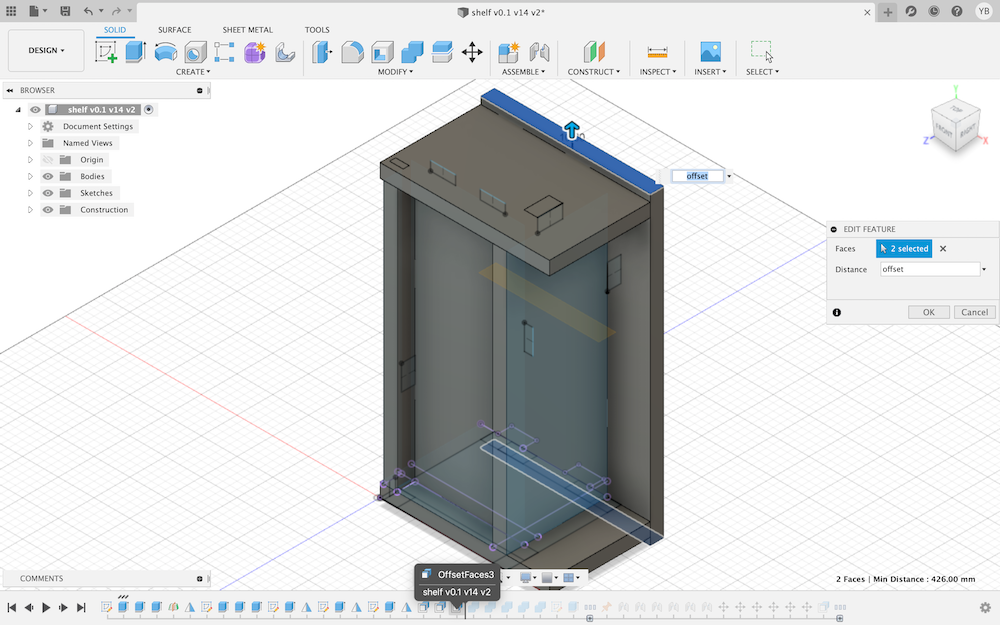
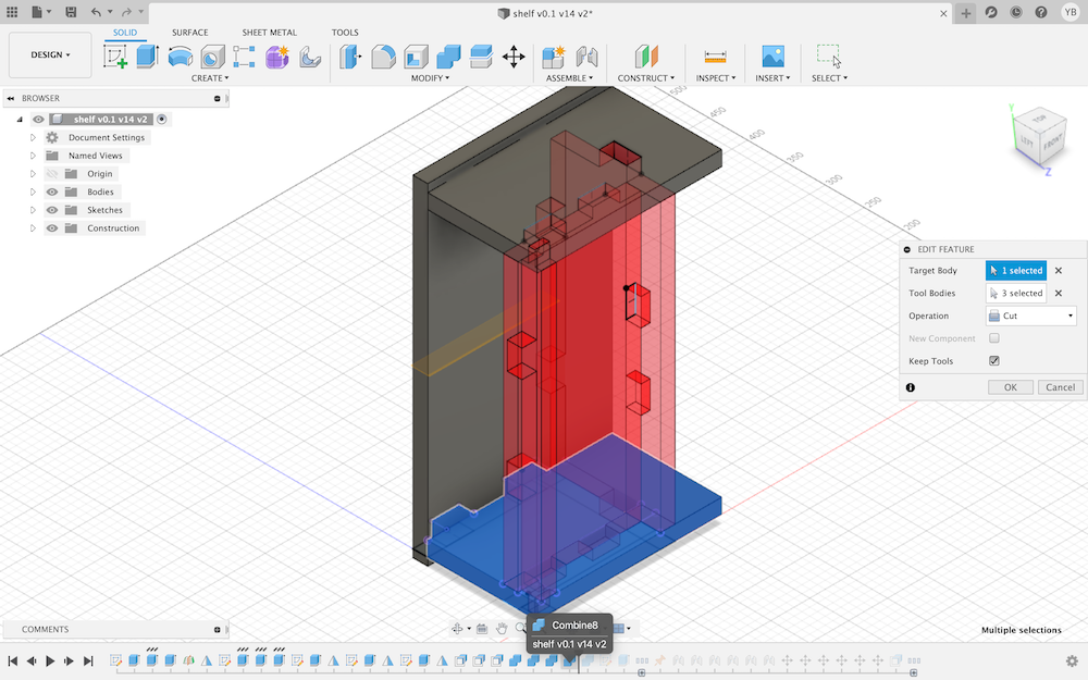
- Create Pockets
Automatically cut away the pockets… Cool ey!
Modify > Combine
Note
Target: Bottom Side, Tool: Support, Operation: Cut and Select “Keep Tools”
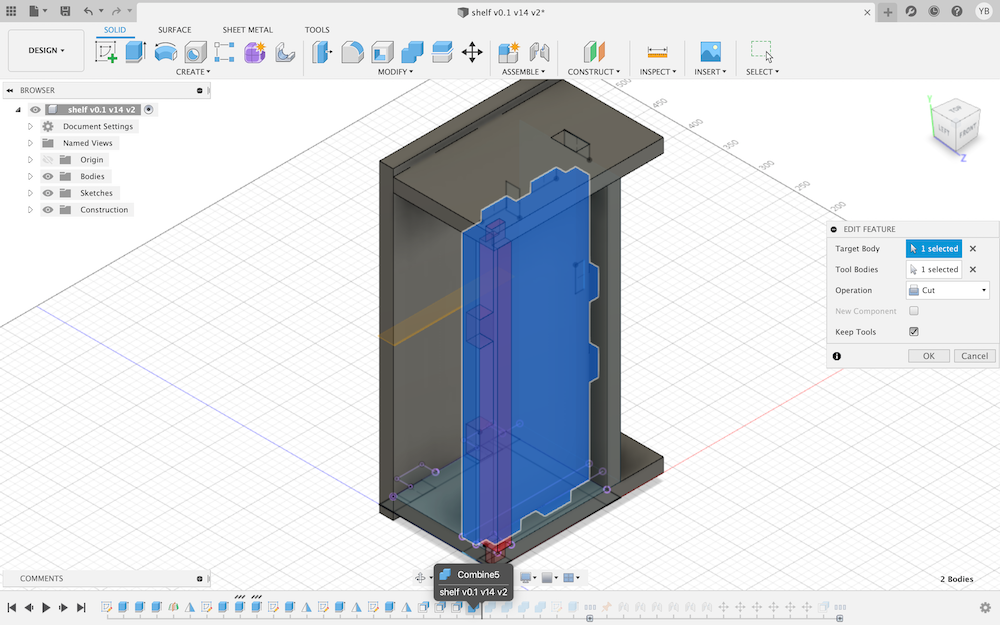
- Create Pockets
Automatically cut away the pockets…
Modify > Combine
Note
Target: Back Sides, Tool: Bottom Side: Cut and Select “Keep Tools”
Automatically cut away the pockets…
Modify > Combine
Note
Target: Bottom & Back Sides, Tool: Support, Operation: Cut and Select “Keep Tools”
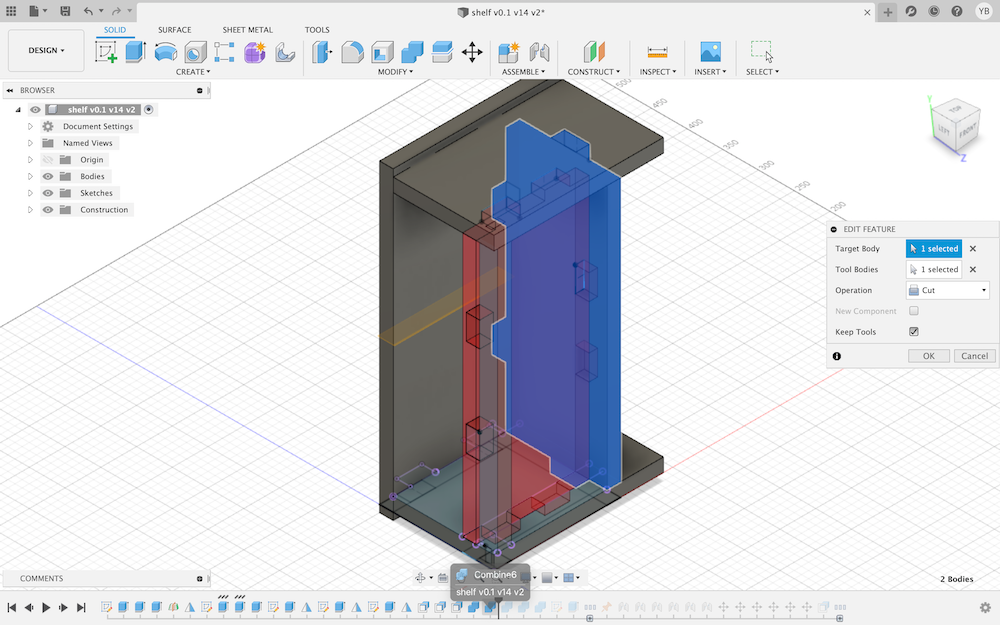
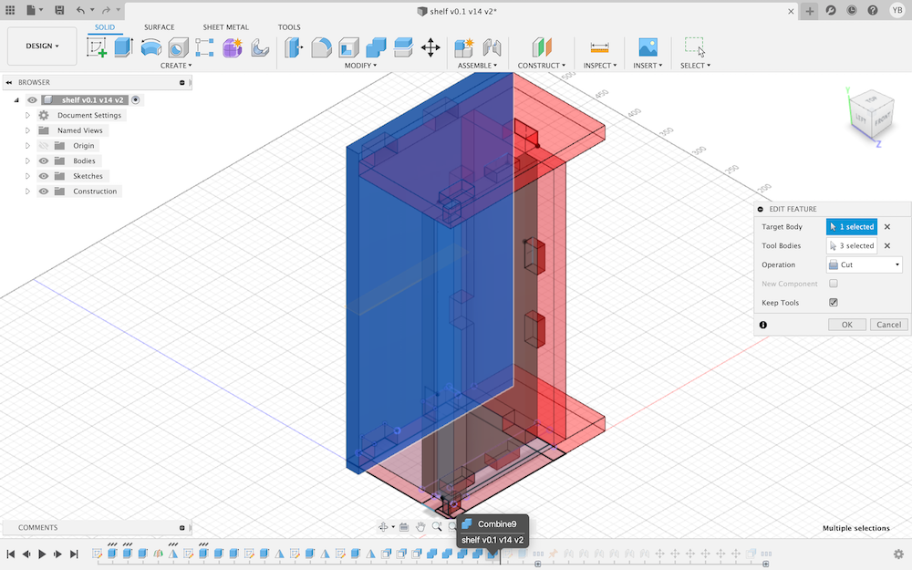
- Create Pockets
Automatically cut away the pockets…
Modify > Combine
Note
Target: 2nd Side, Tool: Support, Bottom & Back Sides, Operation: Cut and Select “Keep Tools”
- Create Pockets
Automatically cut away the pockets…
Modify > Combine
Note
Target: 1nd Side, Tool: Support, Bottom & Back Sides, Operation: Cut and Select “Keep Tools”
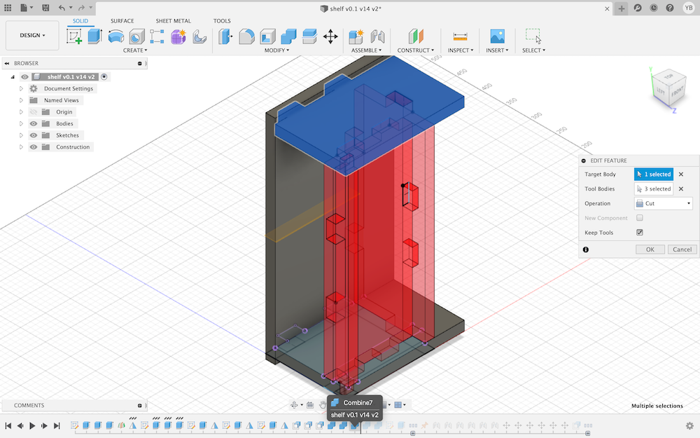
- Create Pockets
Automatically cut away the pockets…
Modify > Combine
Note
Target: Top Side, Tool: 1st, 2nd & Back Sides, Operation: Cut and Select “Keep Tools”
- Create a Stock (Sketch)
This represents the stock sheet that is going to be milled/cut.
- Create a Stock (Extrusion)
Create > Extrude
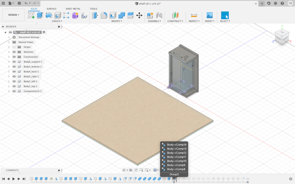
- Create Components
Fusion 360 distinguishes between components and bodies. Following steps will be easier with components.
Tree > Right Click > Create Components from Bodies
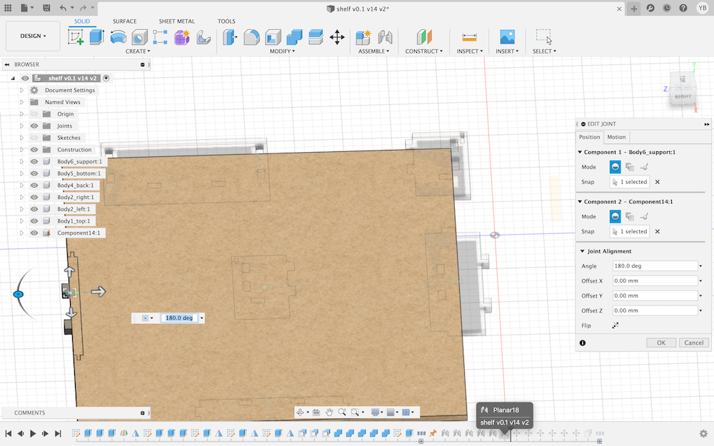
- Create Joints
Joints can be applied to *components. Joints allow for creating relative movement between parts.
Assemble > Joint
Select the desired face and then the Stock.
Note
the Type is Planer
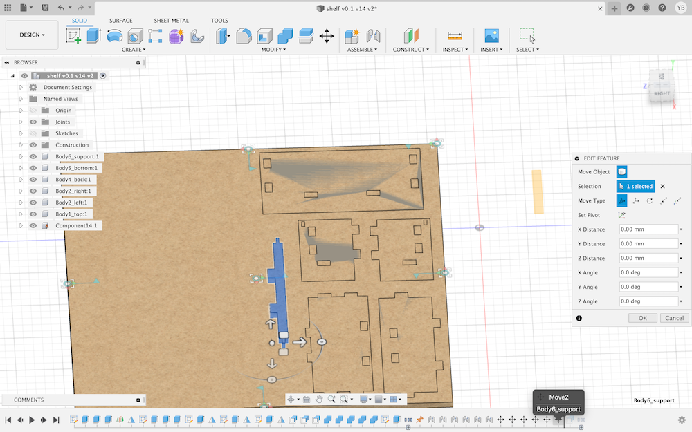
- Placement of Components
Modify > Move
Move, drag and rotate parts to what fits.
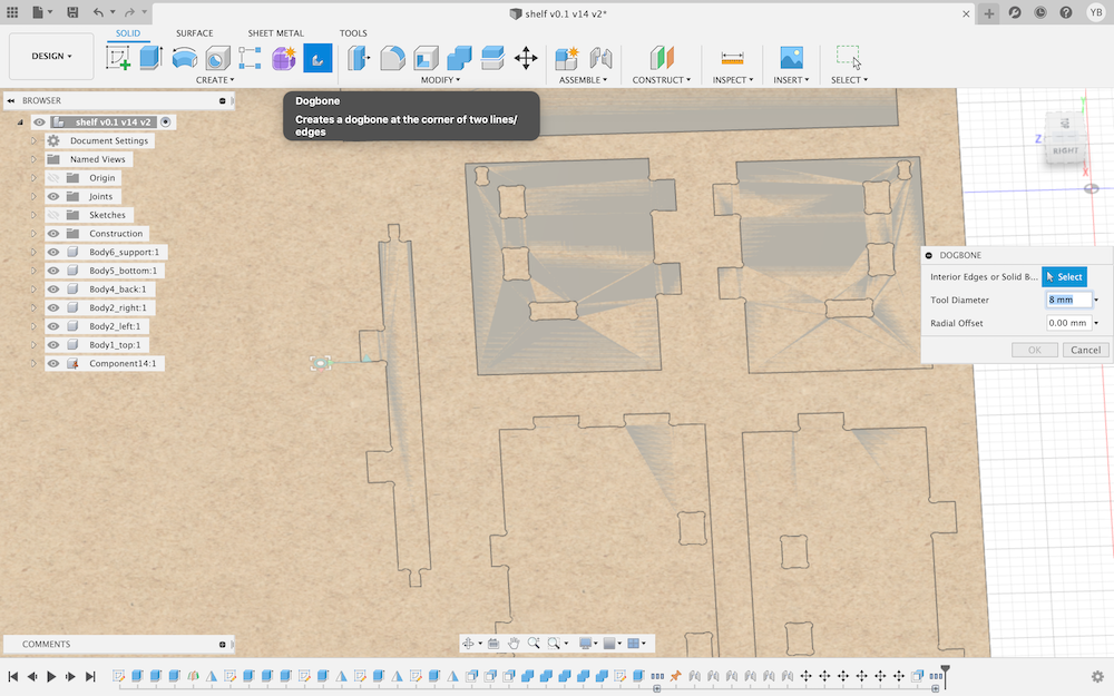
- Create Dog Bone Fillets
An Add-in has been developed to do that.
https://github.com/caseycrogers/Dogbone
Selecting a body will apply a dog bone fillet to it ( Select inside-vertical edge corners).
Create > Dogbone
CAM
Instructor Eino Antikainen provided the CAM Processor File and the setting files with different milling bits available in Fab Lab Oulu.
MANUFACTURE environment
    MODEL > MANUFACTURE
    SETUP > New Setup
Animation shows Setup
Figure 
- To set the work coordinates, set the Origin to ‘Stock box point’.
- Click on the Stock Point and select one of the stock points.
- Check that the selected X,Y abd Z axes match with the actual board…
- Under the Stock tab and change all the offset values to 0mm.
Note
To select the correct milling bit: 1) Select… button under the Tool tab 2) 8mm Flat milling bit from the library
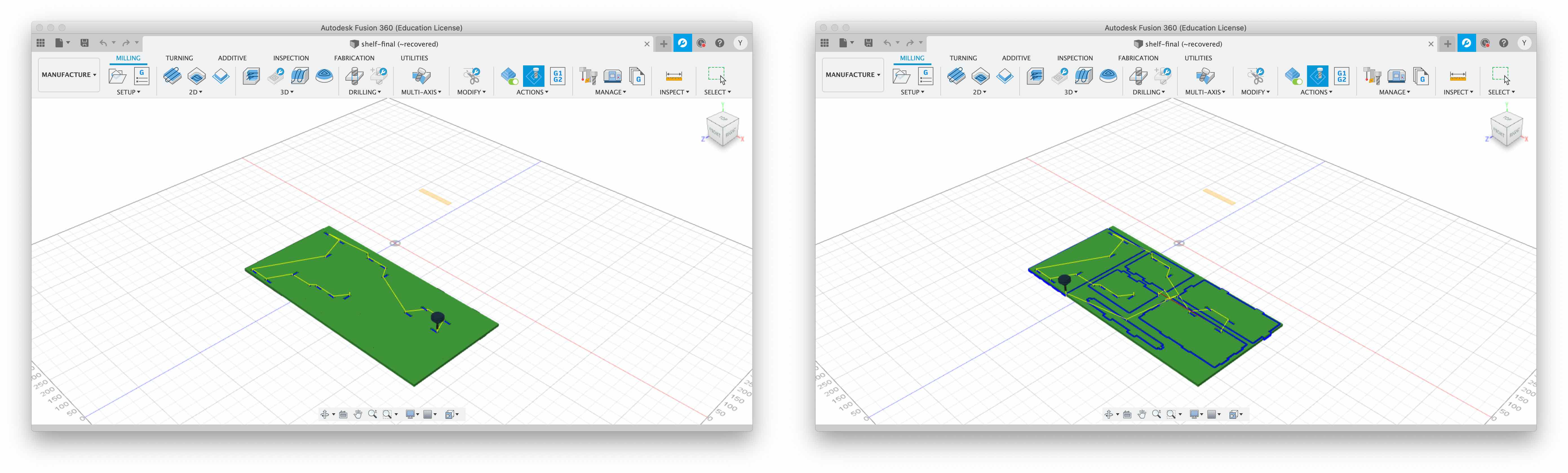
2D Pocket Settings
2D > 2D Pocket
Note
Use a 8mm Flat milling bit from the setting files with different milling bits available in Fab Lab Oulu.
Animation shows 2D Pocket Settings
-
Under Geometry, find Pocket Selections and then, select the areas where you want to make pockets. Set the top and bottom heights, under the Heights tab.
-
Under the Passes tab, the Maximum Roughing Stepdown was set to 3mm; the Finishing Stepdown was set to 0.2mm.
2D Contour Settings
2D > 2D Contour
Animation shows 2D Contour Settings
The process is more or less similar to 2D pockets settings…
Additionally, tabs were added to keep the parts in their place while milling Tabs width was set to 10mm and height to 3mm.
Simulation
Generate the .nc file
ACTION > Post Process
Post Configuration file was provided by instructor, which is used to translate the Fusion 360 dialect into the dialect that the machine understands.
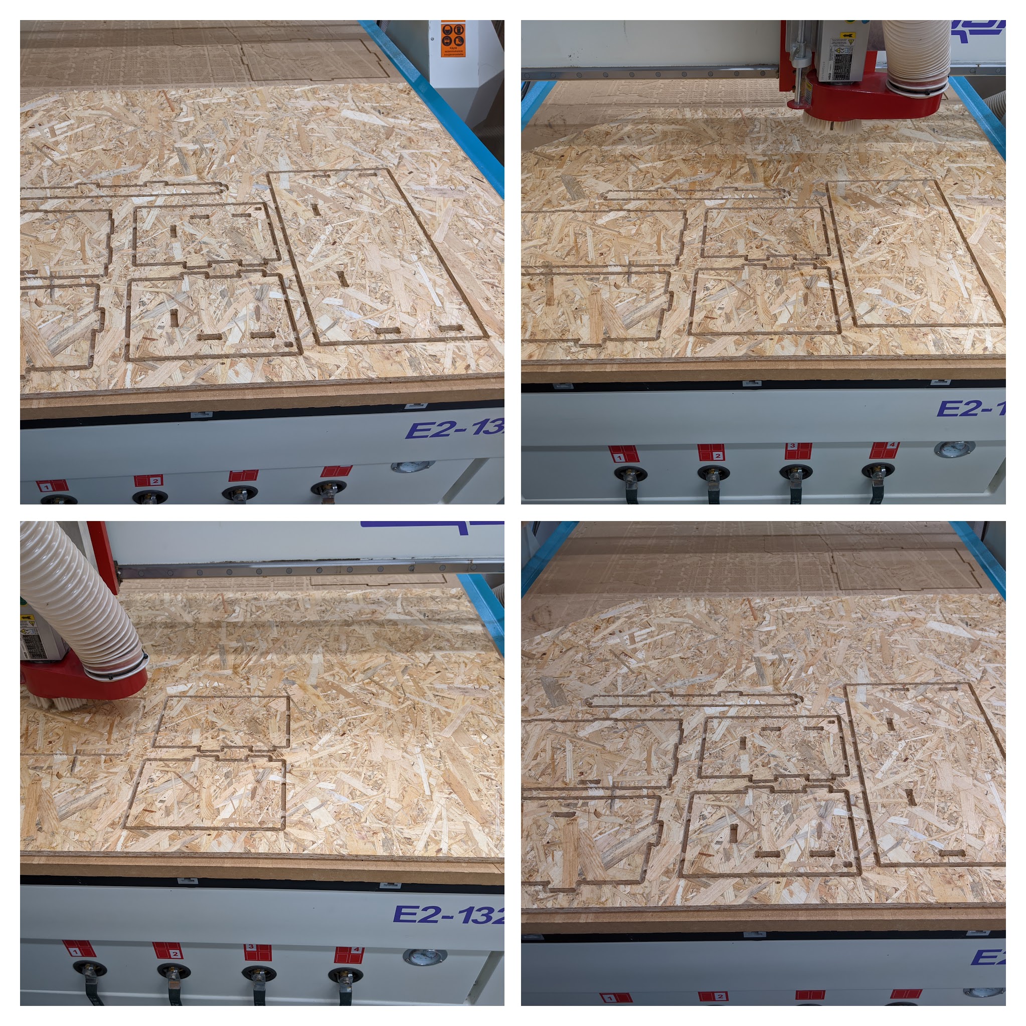
Mill
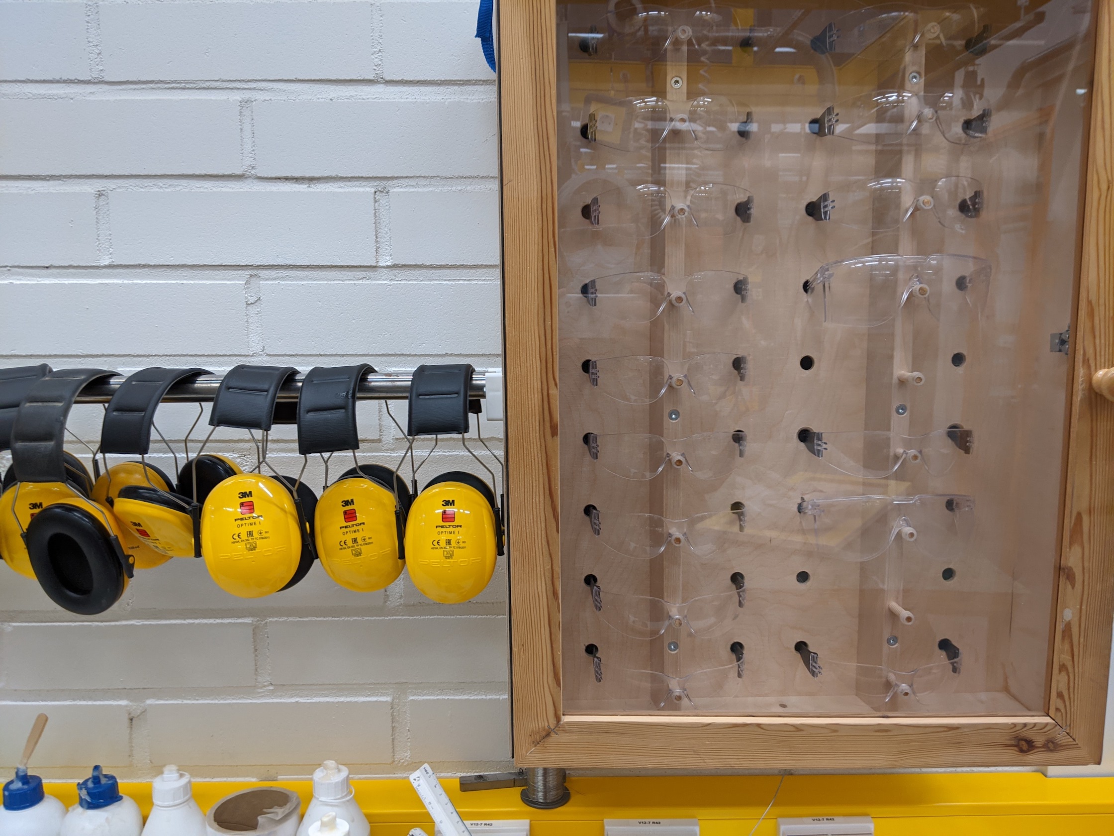
Safety goggles and earmuffs are essential.
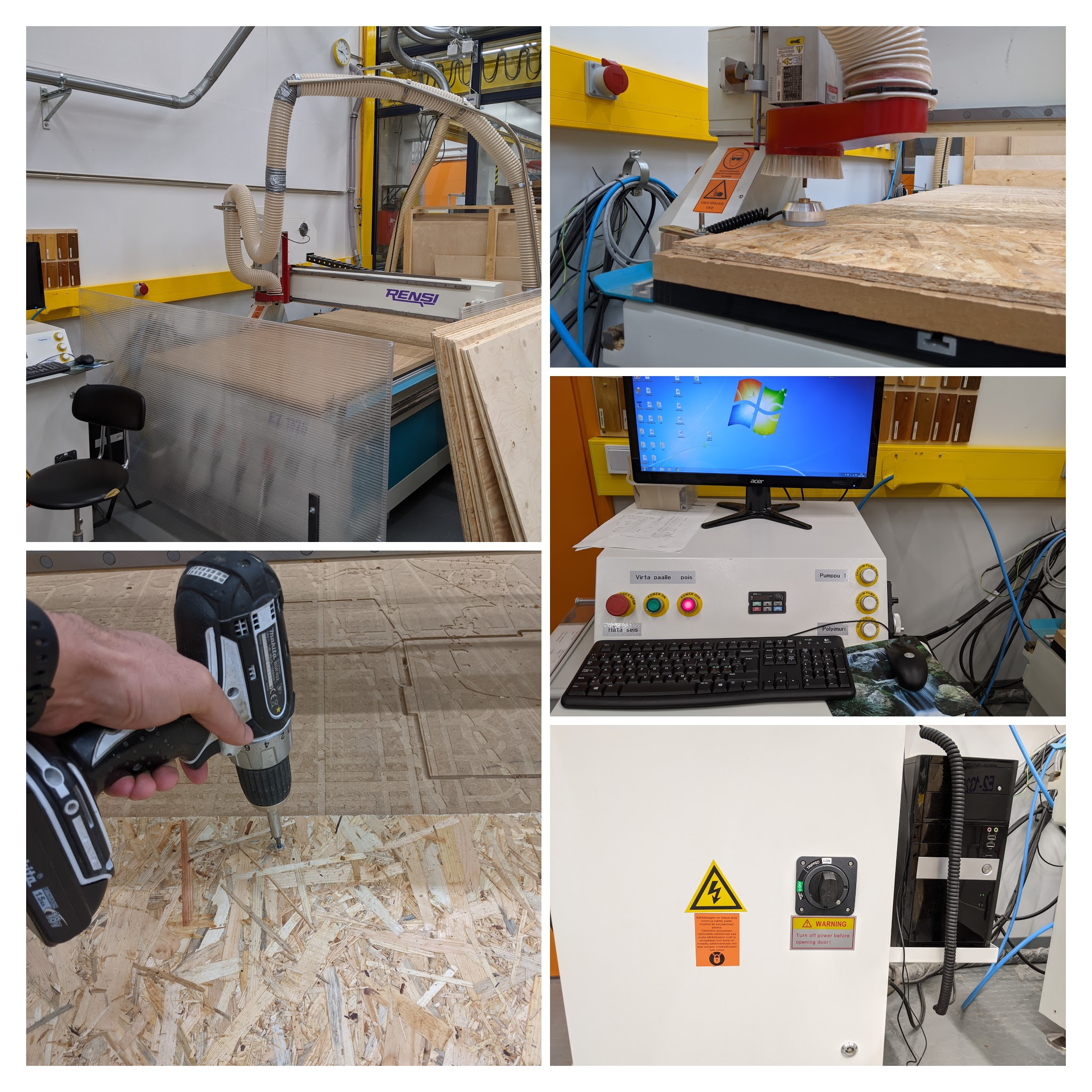
General milling process. Refer to group work for more details, but in summary: the board can be drilled into the surface and the machine is turned on.
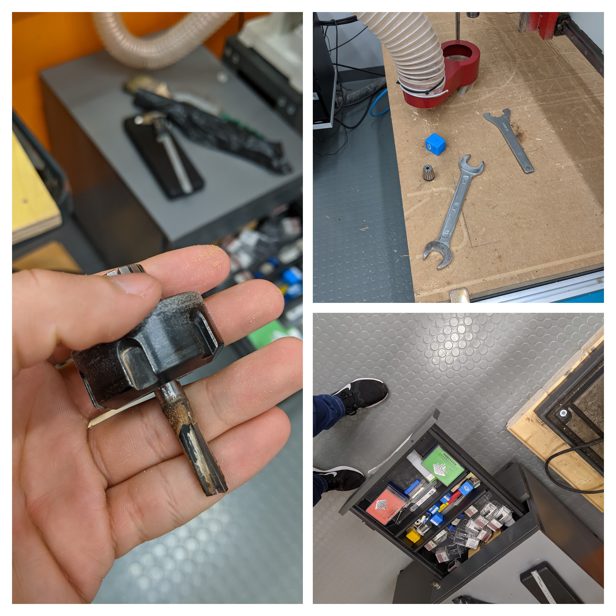
Changing the milling bit to the desired size. There are couple screws to unscrew, the vacuuming brush part is then lowered and wrench keys can be used for untightening the milling bit. See group work for more details.
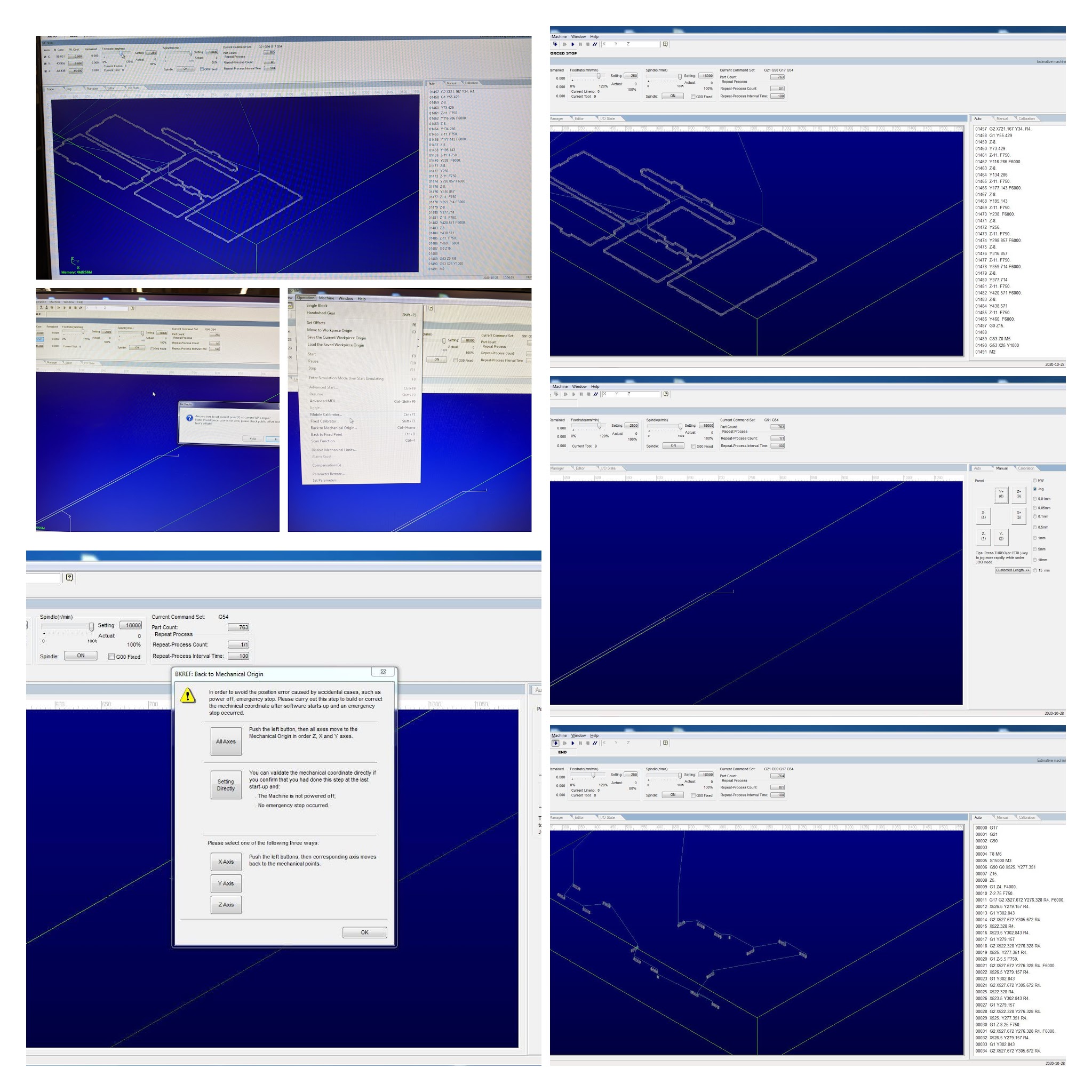
Software Setup: Set the mechanical origin; Open and Load the file; Check the G-code and simulate the outcome and finally Start the milling process. See group work for more details.
Milling in action!
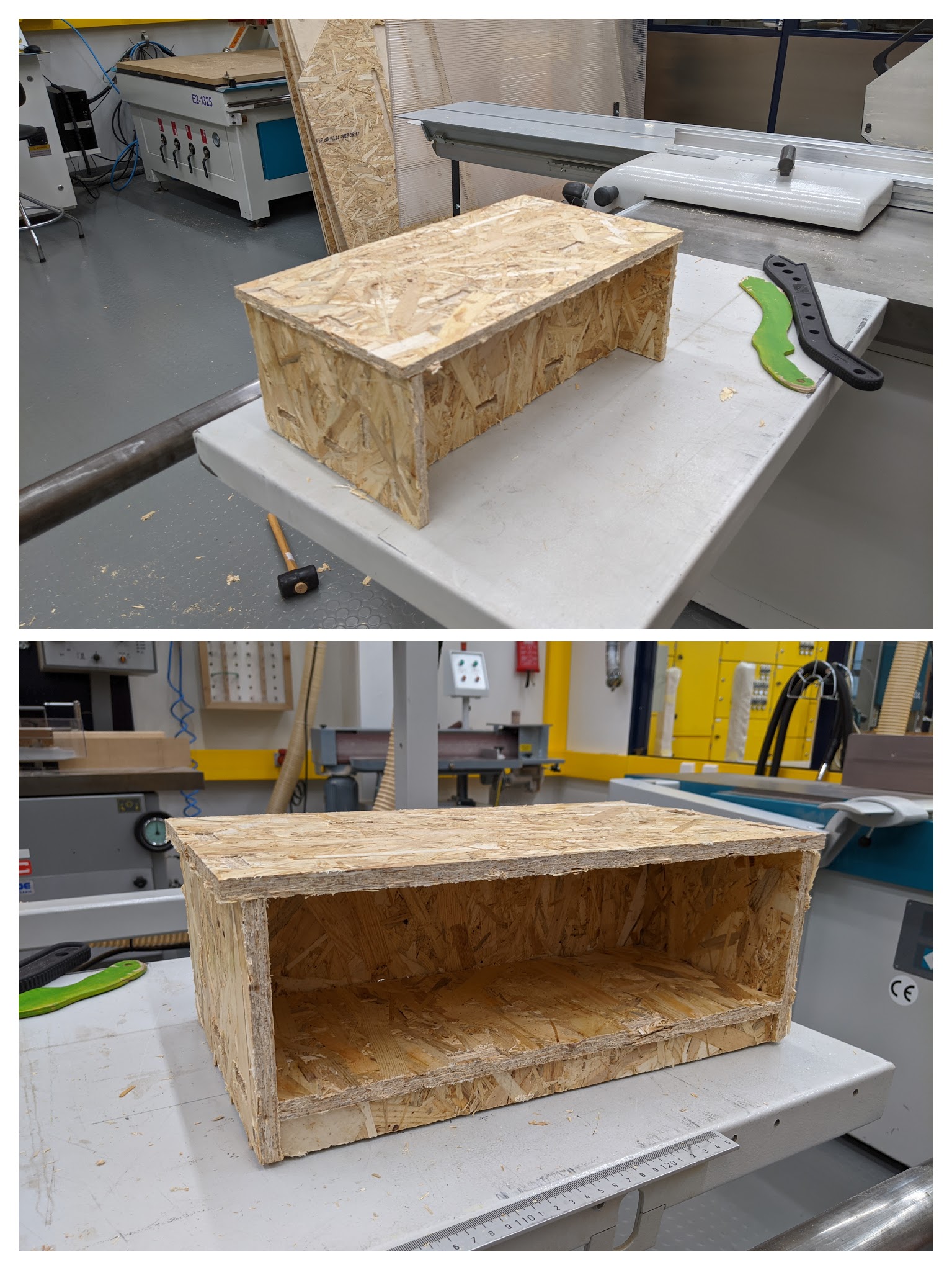
Assemble
Final Assembled shelf. All pieces fit, there was no need for a manual process!
Reflection
Getting the CAM settings was tricky at first. For example 1) Stock to leave setting was on so it would have made all shapes 0,5mm undersize (pockets) 2) the Ramp type should be plunge instead of helix 3) Outlines, order by island setting is not necessary 4) Lead-ins & outs should be disabled because it might cause some problems when using a board.
Additionally, All heights (bottom) were set wrongly. Simulation was checked and it did not cut anything else than just the surface of the board. Therefore, the bottom height was set to model bottom or stock bottom.
Finally, when milling, pockets .nc were not exported alongside contours .nc. Milling had to be done using two separate files.
All in all, this has been a great learning experience.
Files
Group Work
https://fabacademy.org/2020/labs/oulu/students/zhengya-gong/assignments/week07/