13. Output Devices
-
Individual Assignment
- Add an output device to a your micro-controller board,
- program it to do something
-
Group Assignment:
- Measure the power consumption of an output device
Individual Assignment
Useful Links
Output Device Choice
A vibration motor was chosen as an output device.
schematic diagram and components
Using the Output Device
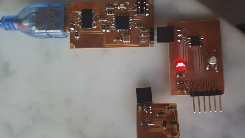
- Motor board was connected to another board for testing (See board from Wild Card.
Electronic Design
-
A board for hosting a vibration motor was designed.
Schematic
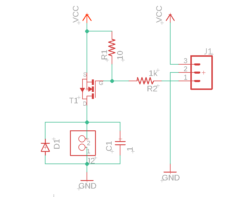
Components
- N Mosfet (NSOT23): acts as a transistor switch
- Capacitor (0.1uF): reduces high frequency electromagnetic wide band noise produced by the motor.
- Diode: MOSFET protection from voltage spikes.
- Resistor 1 (gate resistor): limits switching current.
- Resistor 2 (pull down resistor): kepps MOSFET fully off when signal is not present.
- Connector_2_termFABLAB = for connecting GND and VCC of the Vibration Motor.
- ISP Connector
=== “Vibration Motor Module 01” - NDS355ANCT-ND - MOSFET N-CH 30V 1.7A SSOT3 - 0.26 - 399-4674-1-ND CAP - CERAMIC .1UF 250V X7R 1206 - 0.12 - 497-5559-1-ND DIODE - SCHOTTKY 100V SGL SOD-123 - 0.17 - 311-49.9KFRCT-ND - RES 49.9K OHM 1-4W 1% 1206 SMD - 0.01 - 311-49.9KFRCT-ND - RES 49.9K OHM 1-4W 1% 1206 SMD - 0.01 - ED1514-ND - TERMINAL BLOCK 3.5MM 2POS PCB - 0.46 - 2073-BG300-03-A-L-ACT-ND - 3W, 2.54MM PTH SOCKET, SIL, SMT, - 0.55 / S1011EC-40-ND - TH male header 0.1” (40pos) - 0.65
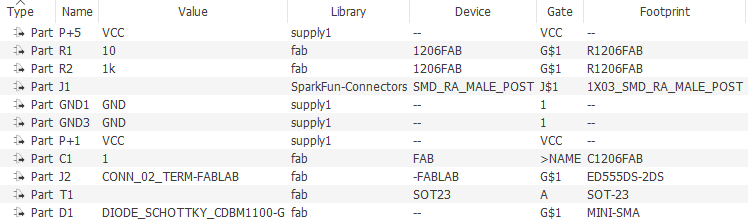
Board
Machine Preparation
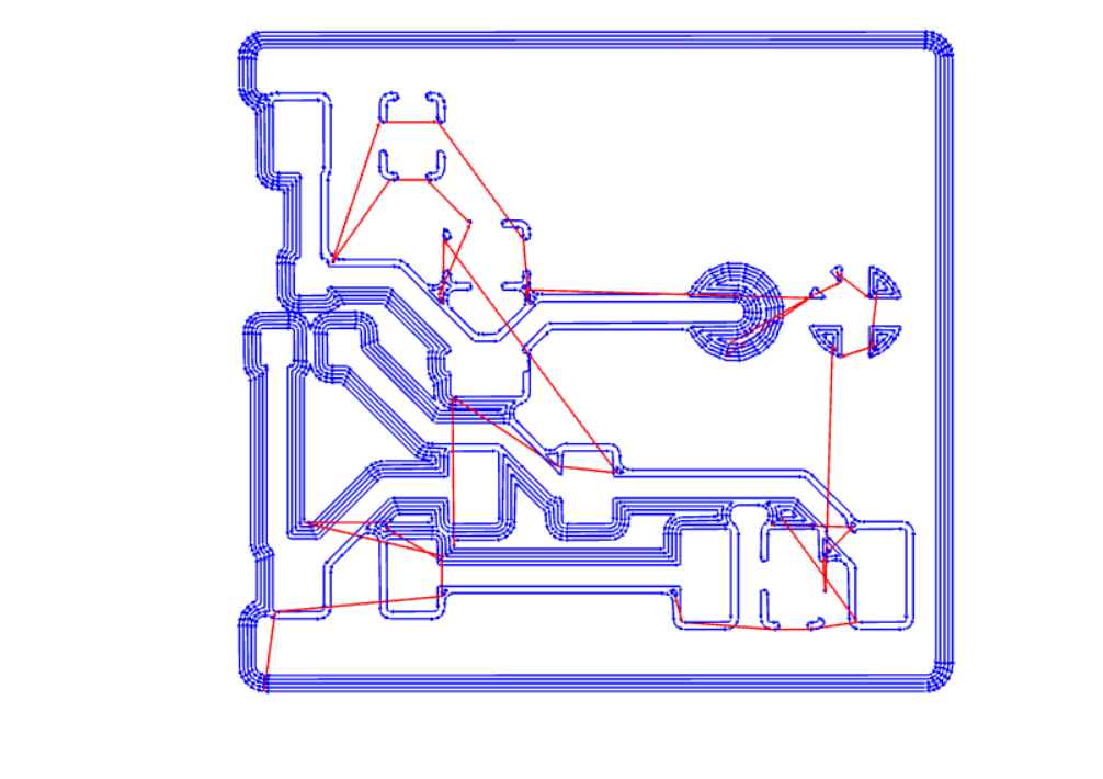
Traces
Traces preparation using mods.
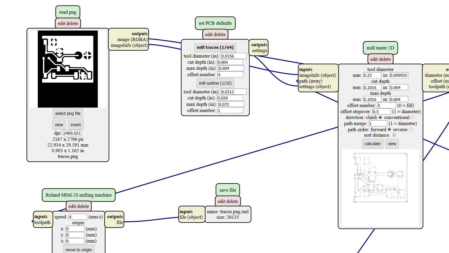
Traces output view using mods.
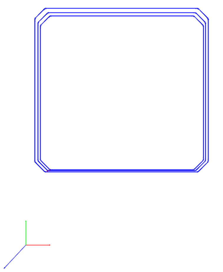
Outline
Outline preparation using mods.
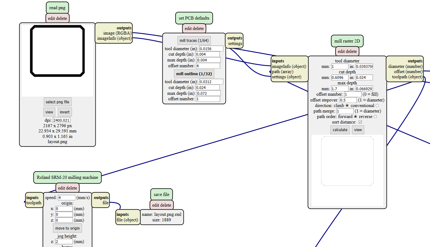
Outline output view using mods.
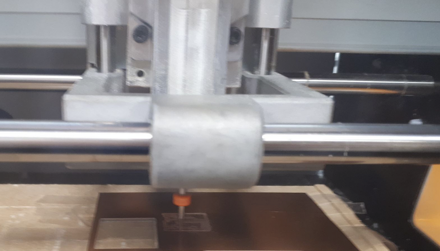
Production
Milling
Board Milling.
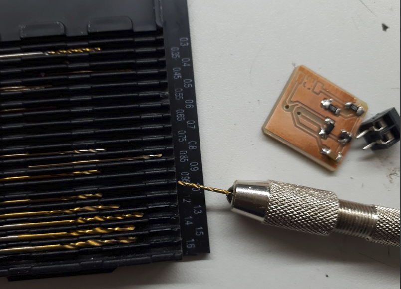
Using Hand drill for milling holes for the connector.
Soldering
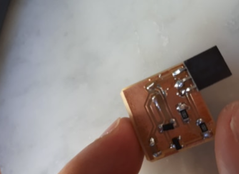
Board Soldered.
Programming
Board Connected to Programmer.
Code Execution
void setup() {
  pinMode( 6 , OUTPUT);  // Must be a PWM pin
}

void loop() {

  analogWrite( 6 , 153 );  // 60% duty cycle
  delay(4000);              // play for 4s

  analogWrite( 6 , 0 );    // 0% duty cycle (off)
  delay(2000);             // wait for 2s

}
Video: Vibration Motor Testing
Files
Eagle Schematic and Board, PNG files and .rml files
Group Work
Measure the power consumption of the motor.
https://fabacademy.org/2020/labs/oulu/students/xinhui-hu/week11_Output_Device.html#group