5. Electronics production
This week’s exercise was about producing a modern electronic component, specifically a microcontroller programmer. Things have moved on a lot since last I made a device myself (a miniature swimming robot in a 10cc syringe). Where back then we used sockets for the chips and soldered all of the standard, full-sized components onto the backs of PCB breadboards, then scratched out the links between the rows of copper strips, today we get to work with highly miniaturised components and much more sophisticated PCB makers.
The adventure this week starts with a visit to Andy Bardagjy’s FabISP page, where he describes the design of a simple ISP which can be made out of the standard components available in the Fab inventory.
The FabISP
The FabISP is built around the ATtiny44 microcontroller. Andy makes the PCB layout available on his website, along with a simple circuit diagram, so that we FabAcademy students (and presumably the world at large) have a place to start. The circuit diagram (reproduced from Andy’s site below) is really very simple. It consists of a single chip (the ATtiny44) with a 20 MHz crystal and a USB connector. The USB data lines are connected through zener diodes and series resistors to convert the logic from 5V to 3.3V (the breakdown voltage of the zeners). The VCC positive power supply to the chip is filtered through a pair of capacitors to ensure it’s clean and reliable.

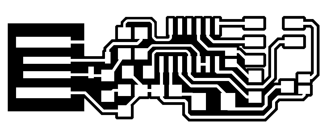
Andy provides a circuit board layout. There are two parts: the tracks (1st image below) which are to be milled into the top of the PCB, and the outline (2nd image) which is to be cut completely through.

Preparing for CAM
The black and white images need to be turned into a set of CAM instructions for the CNC machine to use. This was achieved using the tool on fabmodules.org. The first prompt wants the filename of the circuitboard image. The second prompt is for the type of mill. And the third prompt chooses the process.
I used two different machines for this week’s exercise. In my first go at the FabAcademy in 2018, I used the Kamp-Lintfort FabLab’s Roland MDX-40 mill, but this year, I’ve been slowly setting up a mini FabLab at home, so turned to my new Sainsmart Genmitsu 3018 Pro mill to do the work.
The settings for the Roland are built into FabModules. For the Genmitsu machine, I used the “Othermill (.nc)” setting. Later I learned that “Othermill” is a brand name, so I switched to using the “G-codes (.nc)” option.
The first pass (shown below) is of the tracks on the board (which are to be cut first!).
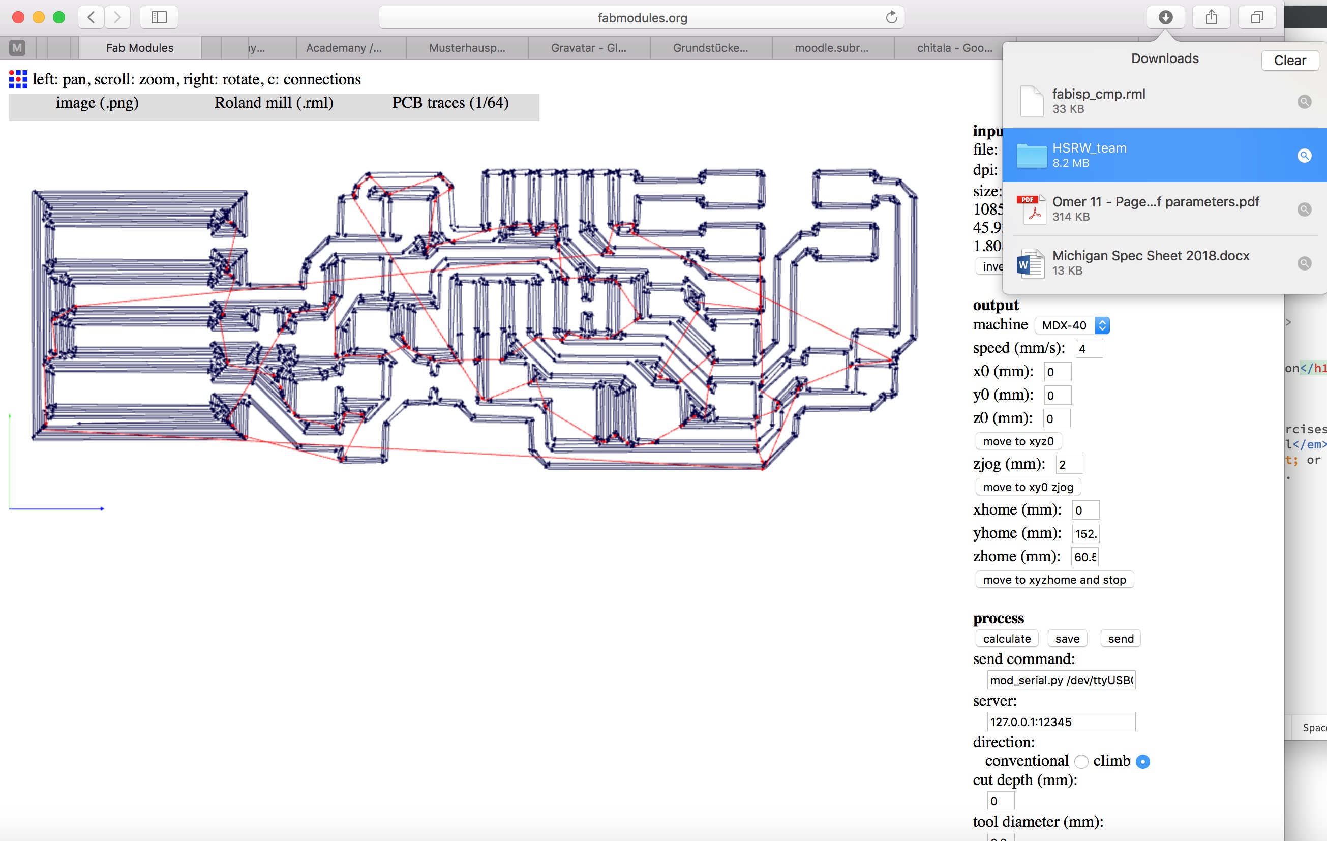
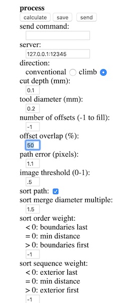
For cutting the PCB traces, the “process” menu needs to be set to “PCB traces (1/64)”. For reference, 1/64th of an inch is just under 400um.
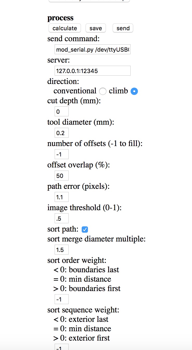
The next step was to set the rest of the parameters. The two mills have slightly different interfaces. For the Roland, the first step was to zero the x0, y0 and z0 values above, set the speed to 4mm/s, then set the process variables as below left. For the Genmitsu (Othermill), there is no zero setting. I didn’t have as robust a milling bit at home, so I set the speed to 1mm/s to spare the delicate router knife I had available. The Genmitsu uses a per-thousand setting for speed, rather than RPM, so I set the spindle speed to go as fast as it could, namely “1000”. I also cut the plunge speed, but later discovered that wasn’t necessary.
I set the tool diameter on both machines to 200um - exactly correct for the Roland end mill; a guess for the Genmitsu router knife. The offset overlap controls how many passes the tool makes over each area - here each “lawnmower” pass covers 50% of the previous pass. The “number of offsets” is set to -1 to make sure all of the copper between the various tracks is removed. Then click calculate to see the calculated CAM tracks. Click save to create the file needed for the CNC mill.
The process was repeated for the outer frame, this time using the FabModules “1/32” setting. On the Roland, a 1mm milling bit was used at feedrate of 1mm/s, while on the Genmitsu, I used a 1.5mm milling bit and a feedrate of 0.75mm/s. A new G code file (.rml for the Roland; .nc for the Genmitsu) was created and saved to disk.
CNC milling the PCB
The CNC PCB mill is a straightforward piece of kit to use. The mill itself is like any other. The appropriate endmill (described above)is secured in the 3mm collet with a pair of wrenches.
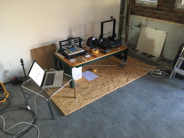
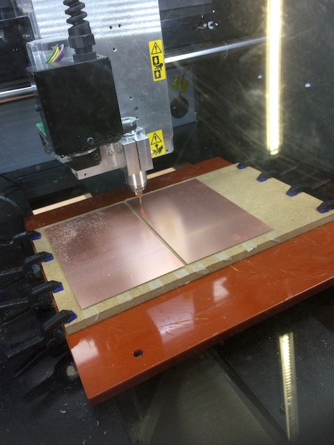
As with any mill, the precision of the part placement and the stability of the clamping are the most important parts of the operation. In both cases, we afixed a new PCB to a 10mm piece of MDF using several strips of double-sided tape. The MDF was then clamped to the mill bed. On the Roland, we used modern spring clamps; on the Genmitsu, I used the older fashioned machine table clamps provided with the machine.
Software: Roland
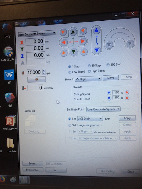
The software that runs the Roland mill is called VPanel. Its GUI is quickly understood. The controls are used to move the table in X and Y, and the head in Z. Before beginning the cutting, the head is placed somewhere central on one of the blank PCBs. The hard part here is touching down in the Z direction. It is possible to convince yourself that you can hear the mill just touching the surface, but better is to move it a bit in x or y and watch for the formation of a bit of copper dust. In my case, I had to stop and start the cutting a few times to dig further into the surface of the copper, until I found a zero which removed all of the copper but didn’t dig too far into the underlying PCB. Once the final zero Z is achieved, then use the “Set Origin Point” section of the GUI to zero the axes.
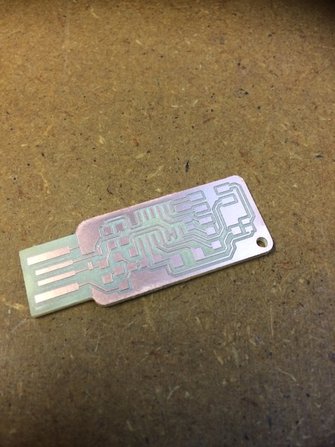
When all is set, then hit “Cut” in the bottom right corner, select the .rml file to be cut, and the machine goes to town on the copper. Change tools after the tracks have been cut, manually find a new z0 using the jog commands on the VPanel, then hit “cut”. The result is below:
Software: Genmitsu
The software provided with the Genmitsu is called Candle. It’s a very simple G-code interpreter with a simple and easy to use interface. It does have some minor quirks, which are annoying but important:
-
Once the mill is connected to the USB port, go to Candle:Preferences and select the correct port. The machine doesn’t remember this after being switched off or disconnected. On my Mac the port was the one that ends with 1420.
-
On starting the program, the machine zero is taken wherever the spindle is at that moment. There is no memory of the previous position.
-
Loading a new code file after running the first one will cause the program to crash, so be sure to return the mill to home (which has to be done manually, as there is no automatic homing system on this simple machine).
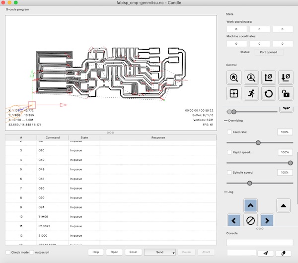
Otherwise everything is pretty straightforward. Once the file is loaded, the G-Code is displayed in the lower half of the window, which is useful for checking the settings (especially the spindle speed - line 12 in the figure below) before starting up the machine.
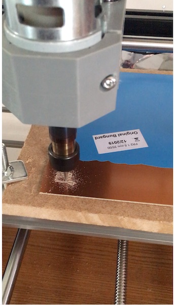
To find the Z0, I borrowed a trick from the 3D printer guys. I placed a single sheet of paper between the tip of the milling tool/router knife and the top of the copper on the PCB. I then lowered the spindle carefully while moving the paper back and forth until the paper started to get caught on the knife point. On the basis that paper is about 100um thick, I then stepped the spindle down that far and set the Z0.
As this was the first time I’d used the Genmitsu to mill anything, I was a little nervous, so I used the override to slow the feedrate down, and slowly let it build up to the 1mm/s I had specified in the G-code. In one early experiment, I let it run at the 4mm/s I had used on the Roland, and that just snapped the routing knife.
After the tracks were cut out, I switched to the milling bit and discovered a new bug in the program as I tried to “home” the spindle: the command G0 X0 Y0, which had worked before, did nothing, and the command G0 X-48.188 (the inverse of where the spindle was at the end of the cut) sent the spindle carriage crashing into the left hand end of the frame, with all kinds of noise and complaint from the servo (remember there are no stops on this machine, nor is there an emergency stop button. Things I’ll have to add…)
As a result, I had to line up the second cut by eye, and I didn’t quite get it right.
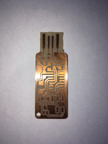
I need to adjust the cutting parameters a bit when using the router knife, as it doesn’t clean all of the copper out of the tracks. I’ll use a smaller diameter setting and increase the offset overlap percentage until it reliably cleans the tracks. In the meantime I’ll continue to use a pocket knife to pop the offending bits of copper out of the tracks (works well if attacked with a sharp tip across the long axis of the copper strip.)
“Stuffing” the PCB
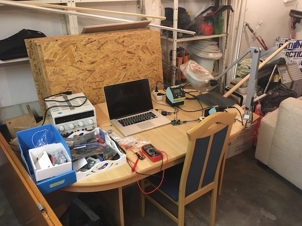
Once the board is ready, the next step is to move to the soldering station (in the garage) to solder all of the components onto it.
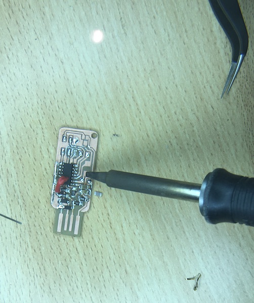
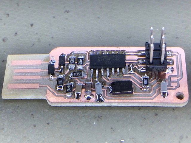
All of the components were readily available in the Fab inventory, and were kindly bagged up by my instructor and shipped to me in the university’s internal post. Soldering was a nightmare. The tip of the general purpose soldering iron I have here was way to wide and made it really difficult to get the solder to flow onto the tiny connections. You can see what I mean in the pic below, which was taken through the large, illuminated magnifying glass that made any of this even at all possible!
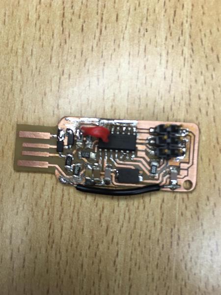
The soldering nightmare was amplified by the errors in the production of the PCB, as described earlier. The pad for pin 13 of the Attiny44 disintegrated as I tried to tin it, so I had to solder on the red jumper wire you see in the pic above. Then later I discovered that the misalignment of the cutout had disconnected the ground plane between the iron and the USB edge connector in the pic. That I fixed with another jumper wire. The final result is shown in the pic below. Note the jumper (between the chip and the 6-pin header) from pins 4 to 10 has been soldered here, ready for programming with the Arduino.
After all of the elements were soldered, I checked every connection with the continuity setting of the multimeter, making sure that the PCB tracks were in fact connected to the legs or ends of each of the components. There were several shorts between the traces - a combination of the hamhandedness of the fat-tipped iron and the narrowness of the gaps between the traces. I cleaned all of those out with the sharp tip of the multimeter probe and retested everything.
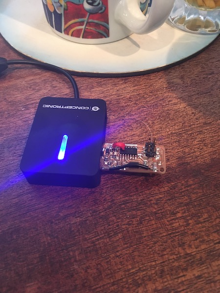
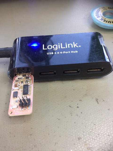
Thinking that the board was ok, I did the “smoke test” using a separate USB hub to spare my Mac the potential damage. Thank goodness I had invested in the hub, as I discovered that I’d missed a final short circuit, and the hub reset itself. I quickly found the culprit piece of solder, cleaned it up, checked everything minutely again, and retested. The device passed fine.
A poor carpenter…
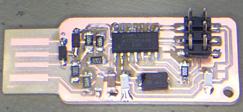
In 2018 I had a much easier time of the stuffing. The board was better made and the soldering iron was the right size. So for completeness, and to show that I’m not just a poor carpenter blaming his tools, here are the results I obtained that year!
Finished board:
Smoke test:
Programming jumper:
Programming the device
Programming the FabISP required the use of another programmer. A chicken and egg problem.

Hardware
The programmer I had to hand was an Arduino Uno. The first step was to wire it up to the new board. The connections are as follows:
| Arduino Uno | FabISP | 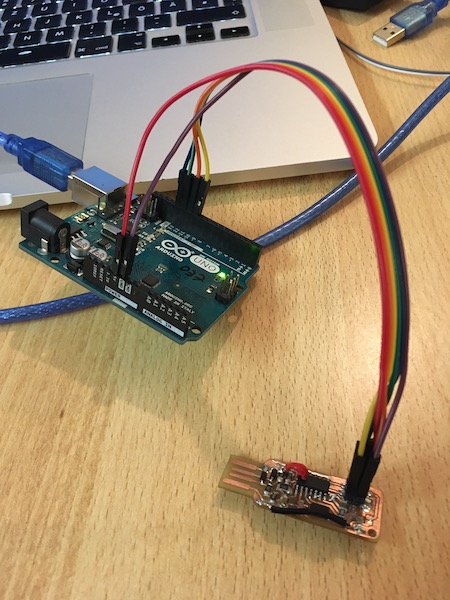
|
|---|---|---|
| GND | GND - Pin 1 | |
| 5V | V - Pin 3 | |
| MOSI - Pin 11 | MOSI - Pin 2 | |
| MISO - Pin 12 | MISO - Pin 4 | |
| SCK - Pin 13 | SCK - Pin 5 | |
| Pin 10 | RST - Pin 6 |
NB: In the end I opted to use the power directly from the USB hub, rather than use Pin 3. The advice was that the power from the Arduino board isn’t sufficient to burn the fuses properly.
Programming with the Arduino IDE
The Arduino IDE comes with a built-in setup for using the board as a programmer. In the examples, there is a sketch called “ArduinoISP”. Uploading that into the Uno prepares it for use as a programmer (NB. that’s an important step, that I neglected to do the first time, which caused a few more hairs to go grey). Then the settings on the Arduino IDE have to be chosen as shown here:
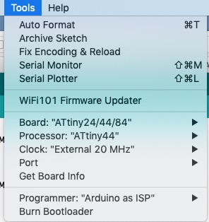
Then it’s just a case of “Burn Bootloader”, and boom. Done.
The “success - avrdude done” message confirmed that my Ugly Duckling FabISP board could be programmed.
Programming from the command line
The assignment this week required us however to do the programming from the command line, rather than through the Arduino IDE. So here goes via a different route.
Setting up the Mac
In 2018, I set up my Mac to do the programming using the command line. This involved installing some software and drivers on my computer. I already had XCode installed for another project, so all I had to install for this course was Crosspack AVR, which I downloaded from a link provided on the archive.fabacademy.org website. The next step was to download the FabISP firmware, also using a link provided on that same website. I extracted the firmware into its own directory in my FabAcademy folder (parallel to the repository, not in it), then started terminal and cd’d to the firmware directory (fabISP_mac.0.8.2_firmware2). I then ran the following command to remove all of the default executables.
make cleanI then modified the Makefile to work with the Arduino. This involved editing one line of the Makefile using vi. The line in question is the third AVRDUDE line in the pic below.
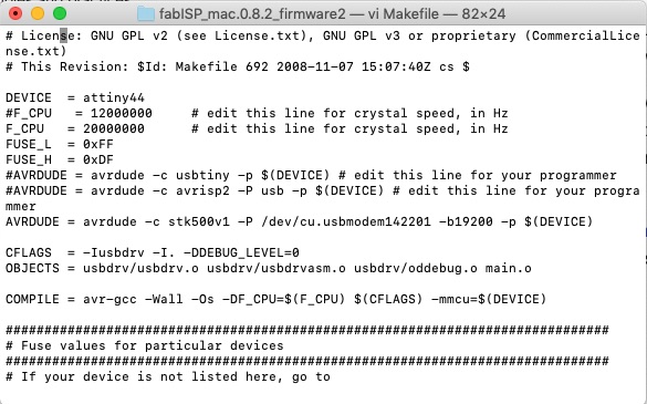
For future copy-paste, here is the line as text:
AVRDUDE = avrdude -c stk500v1 -P /dev/cu.usbmodem142201 -b 19200 -p $(DEVICE)The “stk500v1” is code for Arduino Uno. The “/dev” is the name of the port the Arduino chooses to connect to on the Mac. And -b 19200 sets the baud rate to connect to the Arduino.
Once the Makefile was updated, I ran the simple code:
make hexto create the compiled files ready for uploading to the chip. A quick check to confirm that the “make.hex” file had been created, and I could issue the command:
make fuseThe gibberish started flowing and finally returned the magic words:
“success - avrdude done. Thank you.”
After a quick celebration that the fuses were successfully set, I uploaded the firmware onto the FabISP using the command:
make programThe answer from the device was similarly polite:
“success - avrdude done. Thank you.”
I then unplugged everything and reinserted the FabISP into the USB hub to check that the device could be seen by the operating system. The following screenshot from Apple:About:SysReport:USB shows that all is in order:
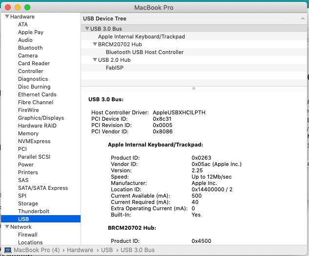
And there was much rejoicing.
Programming something else
The next step will now be to use the Ugly Duckling to program another chip once I’ve got the PCB made and stuffed. There will be plenty of opportunity in the coming weeks as I put the final project together. When I get that far, I will need to unsolder the reset jumper, then either use the Arduino IDE with the USBtinyISP programmer or do it from the command line. In the Makefile, there is already a commented out line with the device called “usbtiny”. This is different from the Arduino line, as there is no need for a baud rate (there is only one available for the usbtiny), nor does the usbtiny need the -P part as it is a USB native device not a serial device like the arduino. When I go to upload a c program to the 2nd ISP, I’ll need to make sure the program is called “main.c” and is in the same directory as the Makefile directory. “make hex” will compile it, and “make program” will upload it to the device.
Downloads
Group Assignment
Here is the link to our group assignment. It doesn’t look like we completed it properly before the virus struck. We’ll come back to it when we’re allowed back into the lab.