15. Networking and communications
This week is about making our boards talk to each other and to the Great Big World…
I2C Arduino Uno to Arduino Nano
To get started, I just dug through the Arduino examples to find the “Wire” library starter kit. On the Uno, which I made the “master”, I uploaded the sketch called “master-writer” and on the Nano, which I made the “slave”, I uploaded the sketch called “slave-receiver”.
The master-writer code looks like this:
#include <Wire.h>

void setup() {
  Wire.begin(); // join i2c bus (address optional for master)
}

byte x = 0;

void loop() {
  Wire.beginTransmission(8); // transmit to device #8
  Wire.write("x is ");        // sends five bytes
  Wire.write(x);              // sends one byte
  Wire.endTransmission();    // stop transmitting

  x++;
  delay(500);
}
The slave-receiver code looks like this:
#include <Wire.h>

void setup() {
  Wire.begin(8);                // join i2c bus with address #8
  Wire.onReceive(receiveEvent); // register event
  Serial.begin(9600);           // start serial for output
}

void loop() {
  delay(100);
}

// function that executes whenever data is received from master
// this function is registered as an event, see setup()
void receiveEvent(int howMany) {
  while (1 < Wire.available()) { // loop through all but the last
    char c = Wire.read(); // receive byte as a character
    Serial.print(c);         // print the character
  }
  int x = Wire.read();    // receive byte as an integer
  Serial.println(x);         // print the integer
}
Note the address of the slave board, which is set in the “Wire.begin(8)” line of the setup subroutine in the slave-receiver sketch. This address is used in the “Wire.beginTransmission(8)” statement of the master-writer sketch.
The wiring of the two Arduinos was straightforward. They’re both based on the same processor, so their pinouts are identical. The two relevant pins for the I2C communication using the “Wire” library are SDA and SCL. These are built-in lines on the ATMega328P chip which runs both Arduinos. As shown in the diagram below, these are SDA = A4 and SCL = A5.
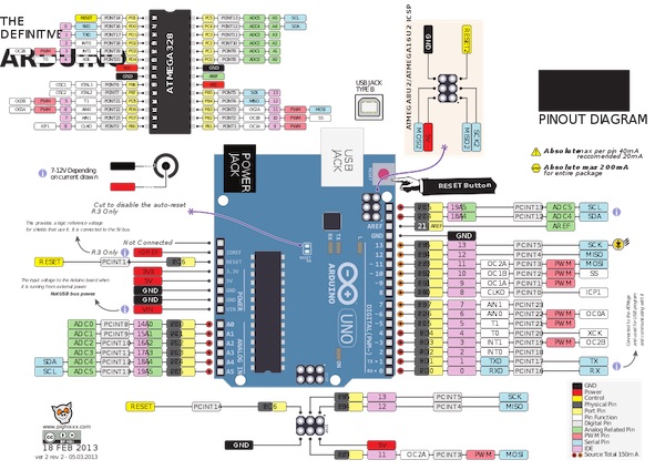
The remaining connection was between the GND pins of the two boards:
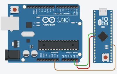
Here is the system working. You can see the LED flashing on the Nano and the numbers incrementing on the serial monitor on the screen behind the two devices.
A third Arduino
In my final project (a six-legged walking machine), I’m designing each leg to be controlled by its own microcontroller, which will both control the local servos and read some local strain gauges. I haven’t yet decided on the hardware, but one possible way to talk to all of the legs is to use the I2C protocoll from the central controller (the brain).
As a first step towards the appropriate bus architecture, I connected three Arduinos in the circuit shown below.
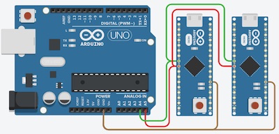
I modified the master sketch to send two batches of information along the bus, one addressed to slave #8 and the other to slave #9. The #8 slave represented the x axis and the #9 the y axis. I didn’t change the slave-receiver sketch except to change their respective addresses.
#include <Wire.h>

void setup() {
  Wire.begin(); // join i2c bus (address optional for master)
}

byte x = 0;
byte y = 255;

void loop() {
  Wire.beginTransmission(8); // transmit to device #8
  Wire.write("x(8) is ");        // sends five bytes
  Wire.write(x);              // sends one byte
  Wire.endTransmission();    // stop transmitting

  Wire.beginTransmission(9);
  Wire.write("y(9) is ");
  Wire.write(y);
  Wire.endTransmission();
  x++;
  y--;

  delay(500);
}
The result is to be seen in the following video. The two slaves (Nanos) are attached to the two USB ports of my Mac, and the master (Uno) is powered by an external power pack. The video shows the set up and the powerpack, then zooms in on the serial monitor, which in the first scene is showing the output from slave #8 (x) and then after I’ve switched the port on the Arduino IDE, the monitor shows the output from slave #9 (y).
The next step will be to have the slaves talk back to the master, so that I can see the output on a single serial monitor.
Radios!
Now to go wireless. Always a fascinating adventure, ever since that first 100-in-1 kit I had as a kid. Now I get to play with slightly more sophisticated toys than that cobbled-together crystal set from back then. Let’s see how it goes.
The kit
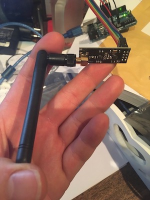
The radios I’m using are NRF24L01+PA+LNA modules from Thaoyu Electronics. There is a datasheet available, but there is an even more useful wiki available here. Here’s what the little beast looks like. I have four of them, but will only be using two for this first little exercise.
I’m using an Arduino Uno as the sending unit and an Arduino Nano as the receiver. They were wired to the radios using the following table:
| Arduino | NRF2401 |
|---|---|
| D08 | CE/CS |
| D09 | CSN |
| D10 | IRQ |
| D11 | MOSI |
| D12 | MISO |
| D13 | CLK |
| 3.3V | VCC |
| GND | GND |
The pins on the NRF2401 are laid out as shown in the following pic:
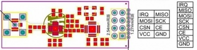
The sending unit was pictured above, wired to the Uno, and the receiver is pictured below, wired to the Nano.
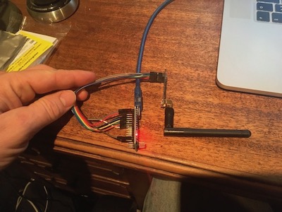
The Nano is connected to the left hand USB port of the Mac, which calls itself /dev/cu.usbserial-AD0JVNQ4. The Uno is connected to the right hand USB port, which calls itself /dev/cu.usbmodem14201.
The code
I started from the examples that came with the radio boards. They’re called SPI_rf24L01_TX and SPI_rf24L01_RX. I won’t reproduce the entire sketches here - instead they are available for download from the following link:
I modified the loop() function of the sender sketch to send a friendly greeting:
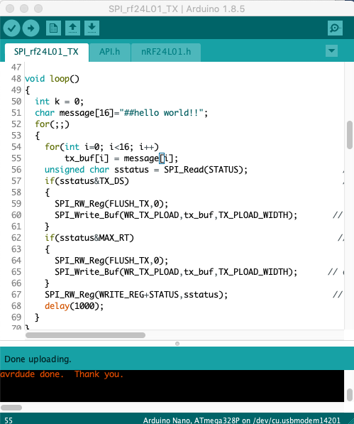
The char message[16]=”##hello world!!” is fifteen characters long, plus the 16th is the carriage return. It’s read, character by character, into the transmit buffer and then pushed to the radio.
Then I modified the loop() function of the receiving unit to receive it:
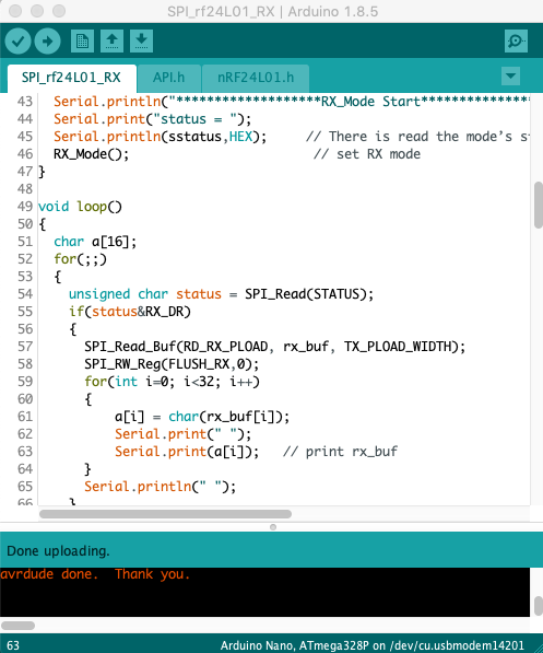
To receive the message, I added a char array called a[16] before the for loop, then read the buffer into the array before printing the array elements separated by spaces.
Success
It’s nice when things “just work”. The proof of the successful transmission was observed in the serial window as shown here:
The next trick will be to modify these sketches myself so that I completely understand what’s going on…
Group Assignment
Our group assignment can be found here.
Just in Case
I thought I might need this: