Zoom flag
Something Useful: Mailbox Indicator for Zoom
The idea for this little project came from a recent Zoom conference in which we tried everything to get someone’s camera to work, only to discover that they’d stuck a bit of electric tape over it <facepalm>. That, and a childhood fascination with the little flags on people’s rural mailboxes - I thought they were the absolute bee’s knees!
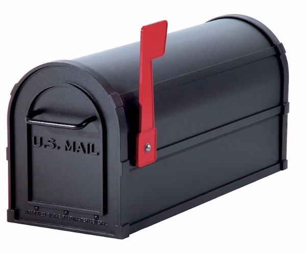
The combination yields a little invention to indicate when the computer camera is operational. Something a little more obvious to everyone, both the videoconference participant and everyone else wandering into the room. When the camera is on, the flag stands proud above the screen, and when the camera is off, the flag folds down in front of the camera, ensuring that any unauthorised use of the camera is inhibited. As an extra selling point twist for those who are really worried about software spying, the device is purely embedded with no transmission nor interaction with the operating system. It relies only on the little LED that lights up next to the camera when its active.
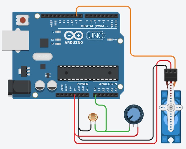
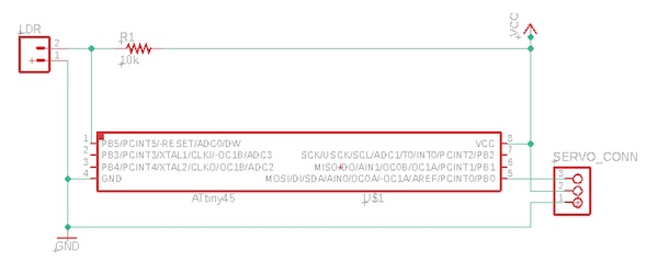
The device makes use of the light sensor to detect whether the LED is active, and a servo motor to move the flag. I’ll detail the mechanical design later, but for this week, the important part is the circuit design and embedded programming. The circuit design is as follows:
The Arduino sketch looks like this:
#include <Servo.h>  // include the library necessary to run the servo

Servo myservo;  // create a servo object
int pos = 0;    // initialise the position to zero

int lightPin = A0;  // set the analog input pin for the light sensor
int lightLevel;     // a variable to store the light level measurement
#define lightCritical 1000  // a level that worked this evening. Will need later adjustment

void setup() {
  myservo.attach(9);  // set up communication with the servo on Pin 9
  pinMode(13,OUTPUT); // set up the onboard LED to provide some visual feedback
  Serial.begin(9600); // set up a light level monitor to allow lightCritical to be tuned

}

void loop() {

  lightLevel = analogRead(lightPin);  // read the light sensor
  Serial.println(lightLevel);         // output to computer

  if (lightLevel > lightCritical) {
      digitalWrite(13,HIGH);          // turn on LED
      myservo.write(90);              // rotate servo 90 degrees
      delay(100);                     // wait for servo to reach max angle
    } else {
      digitalWrite(13,LOW);           // turn off LED
      myservo.write(0);               // rotate servo to zero
      delay(100);                     // wait for servo to reach zero
  }
}
The functioning of the device is demonstrated in the video below.
The green camera indicator at the top of the computer screen is turned on by the software PhotoBooth, simulating a video conference. As the light sensor is moved by hand in front of the indicator, the servo moves clockwise through a 90 degree angle, and as the sensor is moved away from the light (simulating it being turned off - I didn’t have enough hands to hold both video camera and light sensor, and click the mouse) the servo moves back to its starting point.
The mechanical elements of the device leave something to be desired. Since it’s Corona time and I can’t get into the lab, I’ve bought a 3D printer, which I’ll use with Fusion 360 to make a holder and the flag. Hopefully the printer will arrive in time to finish this assignment before it’s due!
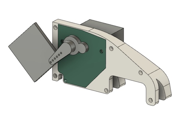
Mechanical Design
Here is a first look at the device in detail:
And here it is in place on top of the virtual screen:
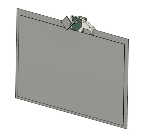
It still needs some cleaning up to get the final dimensions correct, and then of course I’ll need to print it when the printer arrives.
Circuit Design
I’ve started on a design for my own board to replace the Arduino. It will be based on the ATTiny45. I’ll use the LDR and the little servo motor we were given in the “Corona Kit”. All of the components run fine on a Vcc of 5V and because it’s a computer accessory, I’ll include a USB cable for now. There doesn’t seem to be a detailed datasheet anywhere for this servo motor, but online forum posts report a max current draw of about 200mA, so that will also be fine on USB (max 1A). A future design could run on a 6V lithium battery (made of 2x 3V cells)
The first plan is to use the ADC0 channel to read the voltage in the middle of the potential divider. I’ll then look to use the PB0 pin to run the servo.
First step - a recap of how to use Eagle (including the installation of libraries: thanks, Daniele!). There’s a great tutorial on the sparkfun website. Here’s the design in Eagle:
PCB
After switching modes in Eagle and routing the tracks, the board ends up looking like this:
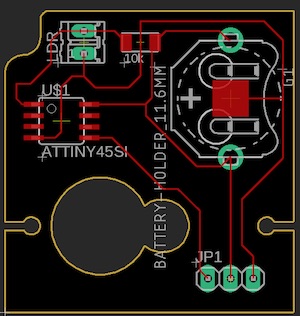
The idea is that the board should fit where the green shape is in the CAD drawings above. I’ll have to cut the board in Eagle to fit. I’m trying to work out how to do the Eagle/Fusion integration!
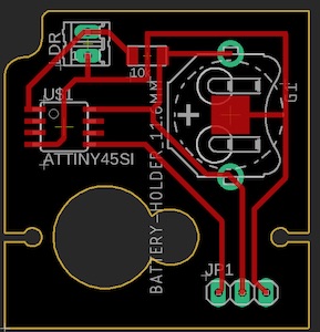
The original traces were too narrow, so I ran the ULP “cmd-change-brd-width” to widen all traces to 20 MIL (noting that MIL is not short for mm!). The result is:
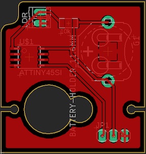
Then to add the copper pour as the ground plane, which is done using the polygon tool to lasso the board, then setting the isolate parameter to 8 MIL, and finally hitting ratsnest, and voila:
Reworked Design
The previous design was far too simple. I’d forgotten that I need to program the chip. Schoolboy error. Sigh. Back to the drawing board.
In Eagle, I added another pin header for the programming. I changed the ADC reading pin to #7 so that the RST pin could be held via a 10k resistor to Vcc. I also added a capacitor across the supply to get rid of noise. I’ve left the two XTAL pins free for the moment, in case the internal clock isn’t precise enough. I then swapped out the battery for a mini USB connector. All of the changes meant that the traces no longer fit nicely on the board, so I had to resort to three zero Ohm resistors. The final schematic and board look like this:
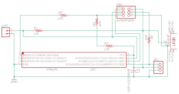
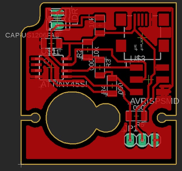
The Eagle files are here:
Milling
Next step will be to assemble and calibrate my mill.
After that I’ll gather the components and do some soldering.
Then I’ll need to go figure out how to use the new 3D printer.