Group Assignment 09: Embedded Programming
The objective of this week’s assignment is to compare the performance and development workflows for different microcontroller families.
Performance Comparison
Boards
To learn about the benchmarking process, we used two types of Arduino boards. Although they carry the same brand name, and can be programmed using the same IDE, they are very different architectures.
Arduino Due
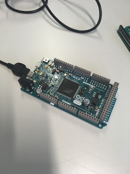
This board is based on the ARM Cortex-M3 microcontroller, and specifically the chip ATSAM3X8E.
Arduino Uno
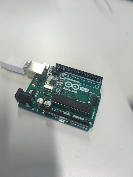
This board is based on the ARM Cortex-M3 microcontroller, and specifically the chip ATmega328P.
Benchmarking Code
To test the calculation speed (benchmark the boards), we used a calculation-intensive algorithm (4th order Runge-Kutta) to solve some ordinary differential equations. The test code is available here.
Testing
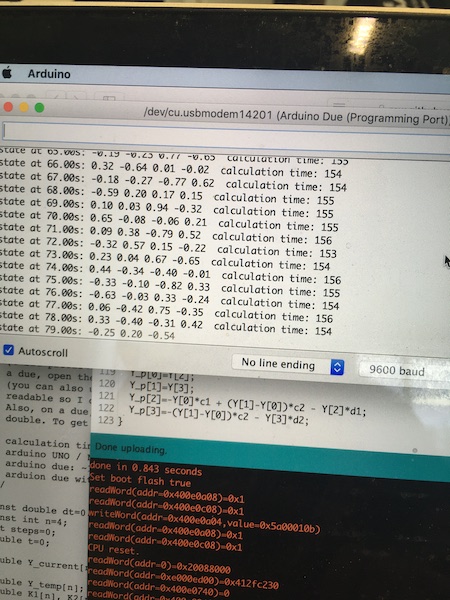
Arduino Due
The Due was a quick machine. The output from the benchmarking test is shown below. Basically it didn’t even break a sweat.
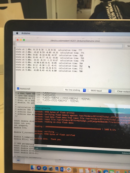
Arduino Uno
The little brother had more trouble. It could run the code, but it was obvious that it was struggling. The processing time was seven times as long as the Due.
Workflow Comparison
The other objective is to compare workflows. In this section, we compared the Arduino IDE with LabVIEW.
Arduino IDE
This system is very much plug and play. The software installs a breeze on the Mac, and all that’s required is to plug in the USB cable between Mac and Arduino. There are some settings in the IDE which have to be set, as follows:
- Tools: Board -> Ardunio/Genuino Uno
- Tools: Port -> /dev/cu.usbmodem14201 (Arduino/Genuino Uno)
- Tools: Programmer -> ArduinoISP
For more advanced programs, it will also be necessary to import some libraries. I’ll detail that requirement when I get that far.
Flashing an LED - Output Device
The Arduino Uno has an LED built into it which is connected to Pin 13. To make this flash required the following simple piece of code:
int LEDpin = 13;

void setup() {
    // set pin 13 to output
    pinMode(LEDpin, OUTPUT);
}

void loop() {
  digitalWrite(LEDpin, HIGH);   // turn the LED on
  delay(1000);                  // wait for one second
  digitalWrite(LEDpin, LOW);    // turn the LED off
  delay(100);                   // wait for 100 milliseconds
}
That gets committed to the Arduino, and voila, as expected, the light flashes on with a short intermittent dark phase.
LabVIEW vs Arduino on Windows
[William] I’ve been working with LabVIEW since the early 1990s and really like the software. The graphical interface works the same way my mind does, namely in flow charts. Anyone who’s been anywhere near me while I’ve been writing text-based code (Basic, Fortran, Pascal, C, C++, perl, whatever) knows just how much I hate semicolons. In the graphical environment offered by National Instruments’ “G”, I can’t make a syntax error, so the compiling always “just works”. (LabVIEW was originally based on the Watcom C compiler. I’m not sure what it is under the hood now.)
LabVIEW is however not the first coding package that comes to mind when thinking about embedded programming on a simple microcontroller. However, there is a compiler available from tsexperts.com or through the LabVIEW package manager. It only runs on Windows, so I had to dig out an old laptop to compile LabVIEW “G” code for the Arduino.
The goal is again to make the LED flash. So now the code is written in “G” as shown below.
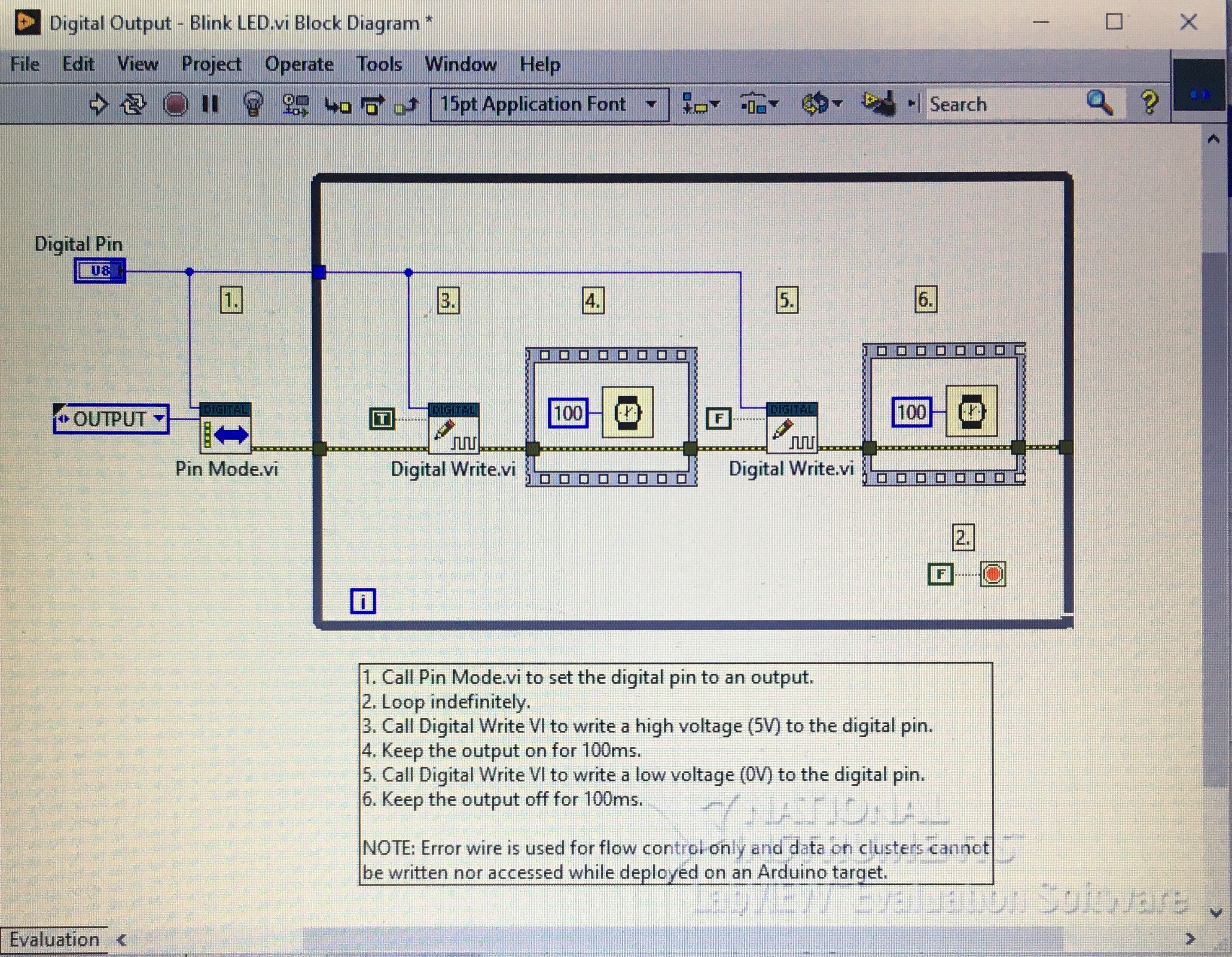
The steps are very similar to the typical Arduino sketch. Starting from the left:
Set Pin 13 to OUTPUT
while (not FALSE) do {
    write HIGH to Pin 13
    wait 100ms
    write LOW to Pin 13
    wait 100ms
}
Next step was to open the Arduino compiler using the link the Tools menu and verify that the communication settings were correct.
- In the Tools menu, set the type of board (Uno) and port (COM3).
Finally, in the Compiler menu, select “Compile and Download” or click on the gear with the checkmark.
Remember how excited we all get when the LED lights up? Well…
Pretty stoked!