11. Applications and implications
Propose a final project. See the lecture notes for this week for requirements
As described on my project page, I am planning to build a 1:15 scale working model of this beast:
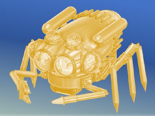
The real machine is intended to carry two people on extended missions under water in wave-swept environments. It will be something like 5m in length and weigh approximately 7 tonnes. The concept is that it should be able to support its own weight walking into the water down a standard boat ramp, so it will need a fairly strong undercarriage and therefore probably hydraulic actuators to move the legs.
Six-legged robots have been around for a long time, and people have worked out how to control them using inverse kinematics to set the motion requirements for each of the motors controlling the joints. The concept with the BREATHE rover is that its legs should make use of simple forward kinematics and rely on sensory feedback to control the motion.
For the 1:15 scale model, which will be approximately 30cm in length, the engineering will be both easier and harder. Easier because obviously the weight and strength of materials will be less significant, but harder because I’ll have to miniaturise everything to fit in the space available.
The main project page will go through the details of the design and development of the model machine. There I’ll follow a standard design report style. Here I’ll follow a more narrative, Q&A approach.
Questions and Answers
What will it do?
The goal for the machine is to move forward on six legs using local sensor feedback on each leg to determine the kinematics. It should do this independently, so that the only command from the user is a compass course. The kinematics will be modelled on the alternating tripod gait of a cockroach or stick insect in the first instance, then later on the sideways motion of a crab.
Specification Sheet
A spec sheet it the first step in setting up a design project. Here’s how mine is shaping up.
| Characteristic | Must/Nice | Parameter | Min Value | Max Value |
|---|---|---|---|---|
| Body Length | Must | m | 0.2 | 0.4 |
| Max Weight | Must | kg | 0.25 | 0.5 |
| Ground Clearance | Must | m | 0.2 | 0.4 |
| Number of Legs | Must | Number | 4 | 10 |
| … | … | … | … | … |
Who’s done what beforehand?
Literature Review
Here’s a quick bit of literature review from the EU proposal I submitted last autumn:
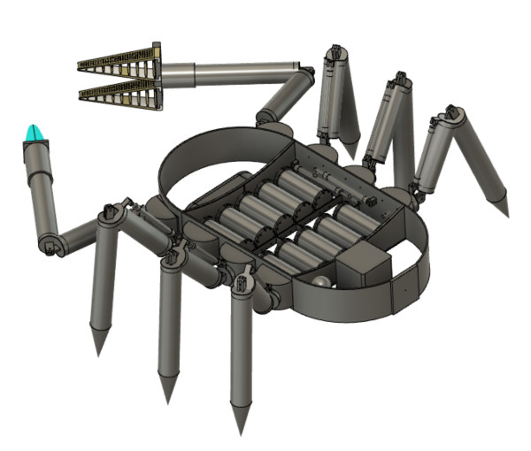
The chassis supports the six modular legs and two manipulators, as well as the main power supply and hydraulics. The legs are based on now standard biomimetic insect models with a hinged knee and doubly hinged shoulder (Full et al 1991, Youngsma 2012). Motion patterns for the six-legged walking motion are based on published work on cockroaches, stick insects and arthropods (Full & Tu 1990, Ting et al 1994, Kram et al 1997, Full et al. 2002, Paskarbeit et al 2010, Günther & Weihmann 2012). The foot of each leg is a conical ISO40 tip which enables the swapping of end effectors such as wheels or claws. Ski-stick-like multi-part basket structures are attached around the proximal end of the foot when the device is operating in soft-bottom habitats to prevent it sinking too far into the sediment.
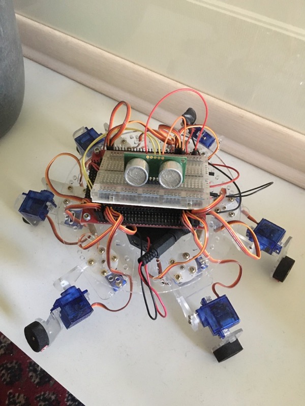
One of the Bionics MSc students a few years ago made this little robot. The student has long left the University, and the instruction manual, if ever there was one, is long gone. I’m going to recycle the components and add some new ones.
There is a really very clumsy, but clever, little six-legged robot out there, which is driven by an ATtiny84: post
Literature Cited
Youngsma K. (2012) Development of a Model and Simulation Framework for a Modular Robotic Leg. MSc Thesis, Worcester Polytechnic Institute. https://digitalcommons.wpi.edu/etd-theses/890
Kram R, Wong B, Full RJ (1997) Three-dimensional kinematics and limb kinetic energy of running cockroaches. J exp Biol 200: 1919–29.
Full RJ, Blickhan R, Ting LH (1991) Leg design in hexapedal runners. J exp Biol 158:369–90. Günther M, Weihmann T (2012) Climbing in hexapods: a plain model for heavy slopes. J theor Biol 293:82–6.
Full RJ, Tu MS (1990) Mechanics of six-legged runners. J exp Biol 148:129–46.
Ting LH, Blickhan R, Full RJ (1994) Dynamic and static stability in hexapedal runners. J exp Biol 197:251–69.
Paskarbeit J, Schmitz J, Schilling M, Schneider A (2010) Layout and construction of a hexapod robot with increased mobility. Paper presented to the 3rd IEEE RAS and EMBS International Conference on Biomedical Robotics and Biomechatronics (BioRob). DOI: 10.1109/BIOROB.2010.5626605
What will you design?
The end goal is a six-legged crawling robot.
To get there, I will need to design its elements and work out how to integrate them into a functional system whole. The elements of the design will include:
- Ankle spike (foot pad)
- Knee (1D rotation)
- Hip (phi & theta)
- Mechanical leg elements (tibia & femur)
- Sensors
- Frame
- Powerpack
- Control
- Communication
Campaniform Sensilla
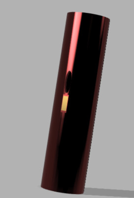
One of the features of insect locomotion is their unique mode of sensing, which is based on detecting strain and/or vibration in their exoskeletons using what is essentially a strain gauge placed over a stress concentration created by the “strategic placement” of holes in the exoskeleton. The main sensor is the Campaniform sensilla. My biomimetic version of it will use a standard strain gauge placed in the stress concentration axially below or above the hole in the leg wall (the leg will be a cylinder).
The sensilla may be a while coming, so in the first instance, there will be simply a microswitch on the tip of the foot.
What materials and components will be used?
The goal will be to stick as closely to the FabInventory as makes sense, and then augment that as required to achieve the design objectives for each of the elements of the project.
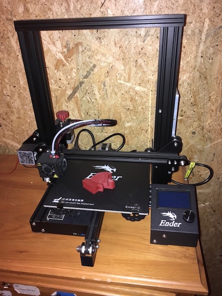
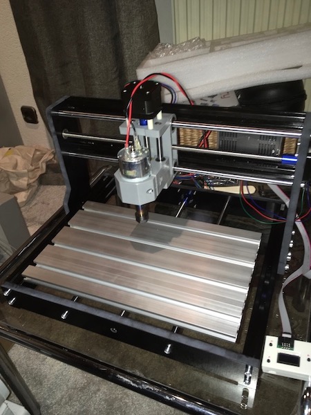
There will be several prototypes, I’m sure, on the way to the final project. Due to the current lockdown constraints, I’ll work first with the Arduino Uno and servo motors I’ve got. I have a little 3D printer (Ender 3) and a small CNC mill (Sainsmart Genmitsu 3018-Pro) at home, so I’ll make as many of the parts as I can myself. I should also be able to make the PCBs and solder them together.
Where will they come from?
I’ll use the FabInventory as much as possible. During the lockdown, our lab has made arrangements for the inventory to be available. What I can’t get from the lab, I’ll order from amazon or conrad.
How much will they cost?
Aim is for a budget of a few hundred euros.
Preliminary bill of materials
| Assy | PartNo | PartName | Description | Qut | Unit | Buy/Make | Cost |
|---|---|---|---|---|---|---|---|
| Motors | FS5109M | Standard Servo | 9kgcm hold T | 18 | ea | Buy | 252.90 |
| Electr | FR2 | PCB stock | FR2 1.5mm 160x100 | 3 | ea | Buy | 12 |
| Electr | ATt84 | ATtiny84 | Microcontroller | 6 | ea | Buy | 2 |
| Electr | LED | LED | LEDs blu-grn-yel-red | 6x4 | ea | Buy | 5 |
| Electr | Cap10u | Capacitor 10uF | 6 | ea | Buy | 2 | |
| Electr | Cap22p | Capacitor 22pF | 12 | ea | Buy | 4 | |
| Electr | Xtal | Crystal | 16MHz timing crystal | 6 | ea | Buy | 6 |
| Electr | R2k7 | Resistor 2700Ω | 24 | ea | Buy | 1 | |
| Electr | D2FS-FL-N-T | Microswitch | SPST microswitch | 6 | ea | Buy | 4 |
| Mech | Pipe | Al pipe | 15mm OD, 2mm WT | 2 | m | Buy | 20 |
| Mech | MDF | MDF Base | 20mm MDF board, 30x20cm | 600 | cm2 | Make | 5 |
| Mech | PLA | PLA MFlex | PLA 1,75mm | 200 | g | Buy | 4 |
Everything but the motors is already available either in the FabLab or in my lab. The total cost for the materials is estimated at approximately 300€.
What parts and systems will be made?
I’ll make the skeletal elements and body.
The robot will be driven by standard, 9kgcm torque servo motors (FS5109M).
Power will be provided by a USB cable.
The CPU will be an Arduino Uno.
Leg control will be done using ATtiny84’s and boards I’ll make myself.
I’ll make the sensor system myself.
What processes will be used?
- Input devices
- Output devices
- PCB milling
- Embeded programming
- 3D, CNC, moulding, laser cutting.
Until the FabLab reopens, I’ll use the tools in my own workshop, namely the Ender-3 3D printer and Genmitsu CNC mill.
What questions need to be answered?
If by “question”, you mean “Research Question” in the academic sense, then what I’m hoping to achieve is a machine that can implement what we know about 6-legged locomotion kinematics. Once I’ve got it working that far, then I can start to ask hypothesis-driven research questions about optimisation of design, etc.
Other questions that came up during one of our Remote FabLab skype calls were: Can I build a small piezo motor myself? What do I have to do myself? Is there an open-source firmware for a hexapod? Can I program/apply it? Will the forward kinematics approach work? How do I best implement spiral development (iterative prototyping)?
How will it be evaluated?
I will evaluate my own success based on the criteria I will have set out in the specification. Did the machine achieve the design objectives? If it did, the evaluation will focus on what could have been made even better, and if it fell short, then I will look to assess the lessons learned and try to implement those before the clock runs out.
For myself, the evaluation will be about what I will have learned in making this work? The FabAcademy adventure has been a long one, and I’m determined to actually complete it. When (because there’s no “if” here) I get this done, then I’ll look forward to the “whoop, whoop” that will accompany the hero shot video.