Group Assignment 13: Interfacing
The objective of this week’s group work is to compare how the various interface tools work. We’ve selected three to highlight.
Arduino IDE
The Arduino IDE is a deceivingly powerful interface tool specifically designed for embedded programming. The coding is all done in a text-based language closely resembling C. A simple program to generate a sine wave output over the serial connection looks like this:
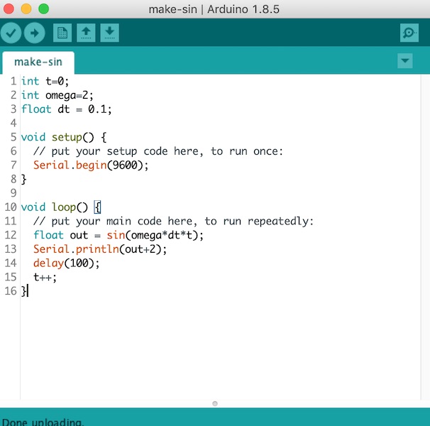
In this code there are three sections. The first couple of lines at the top define some global variables.
The setup function runs once to set up the Arduino. A built-in library supplies the underlying code for the serial interface, and a single line of code is required to set up the serial communication with the computer.
The loop function continues to run as long as the machine is powered up. This simple function just calculates the value of a sine wave shifted into the positive y domain, then outputs that to the serial communication link.
Arduino IDE as a simple UI
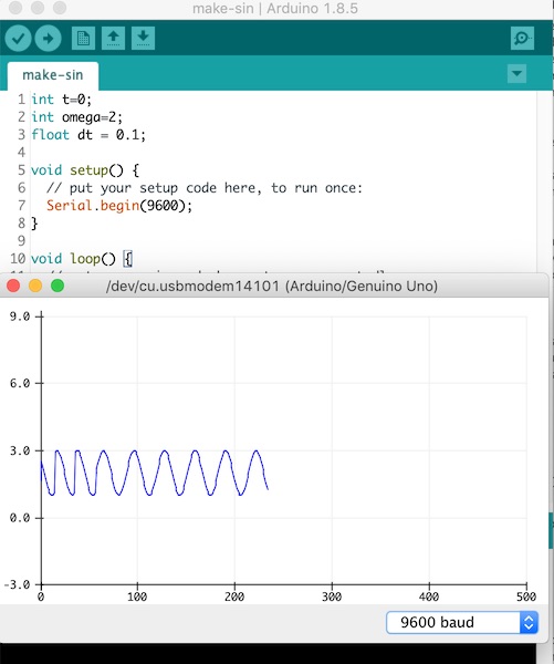
The Arduino IDE contains a very simple UI, which is intended only really for debugging. The UI consists of a plain window which is activated through commands in the tools menu. In one format it presents the text as sent in the Serial.print commands, and the other presents a waveform chart not unlike an old style chart recorder:
LabVIEW
National Instruments’ LabVIEW is specifically designed to interface with measurement devices. The program is essentially a graphical C++ compiler. There are two windows (panels in NI-speak): the left hand one below is the “front panel” (user interface), in grey to represent the old style 19” rack devices we used to use; the right hand one is the “wiring diagram” (coding environment).
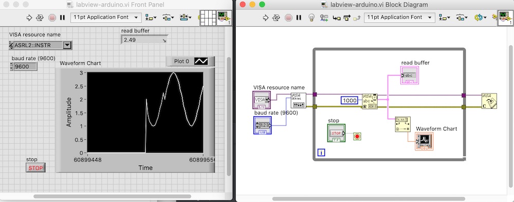
The design of our interface starts with a while loop (grey frame) and a stop button (in green). The main part of the serial interface to the Arduino is done through the three square icons (which represent functions/subroutines) in the centre of the wiring diagram. Outside the while loop, we start by initialising communications with the Arduino (VISA SERIAL). The next block is the command to read the serial buffer. This is converted to a floating point number and displayed on the front panel (Waveform Chart). Finally, again outside the loop, communications are closed with the Arduino after the stop button is pressed.
The connection to the Arduino is over the USB port.
The code is uploaded and run with the arrow at the top left of either panel.
Processing
The Processing 3 IDE is a text based programming environment which works well. It’s more work that the LabVIEW option, but can be used to provide a similar UI experience.
Processing works just like the Arduino IDE, in that there is an initial setup procedure that runs once, and then a draw procedure that repeats forever. All other procedures in the root part of the program also run in parallel, forever.
The code required is shown in the two screenshots below.
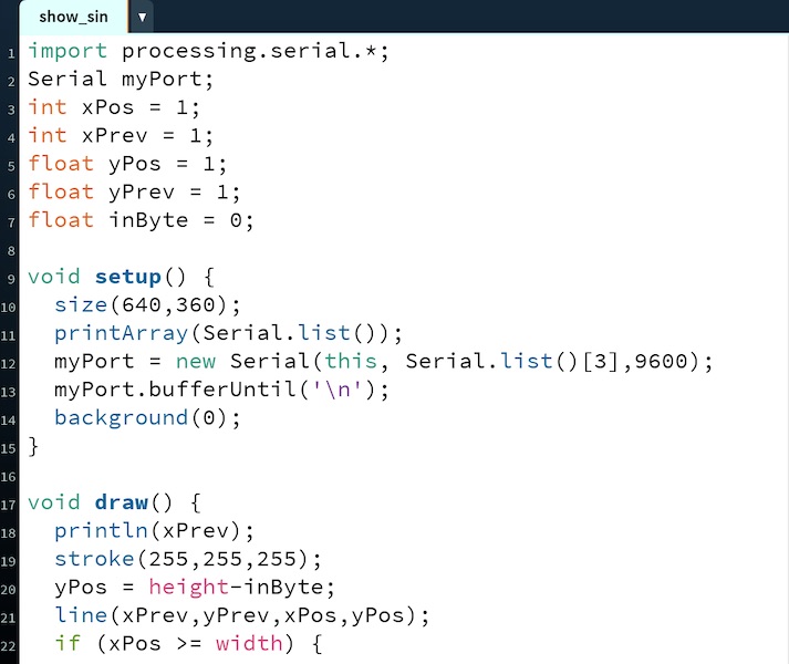
The first two lines create a serial object to use for communication with the Arduino. The next few lines are variable declarations.
The program starts with the setup subroutine, in which we define the serial port and create a connection to the Arduino.
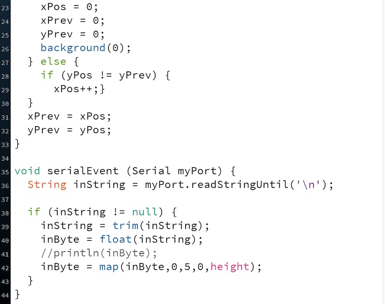
The draw subroutine opens a new window and draws the data as a set of white lines on a black background. The code looks complicated, but it’s all just required to keep track of where the drawing cursor is from one update to the next. Trick is not to update any positional information until a new datum arrives over the serial port, which is the reason for the if (yPos != yPrev) condition.
The final subroutine reads the serial port and updates whenever there’s a new byte.
The output is shown in the screen shot below. The system isn’t quite the chart recorder of LabVIEW or Arudino - we’d have to keep track of the presented data more carefully in order to shift it along to the left. That would just require the use of an array.
Downloads
- Arduino sketch
- LabVIEW VI
- [Processing]