Project Diary
Time to start designing the little beast.
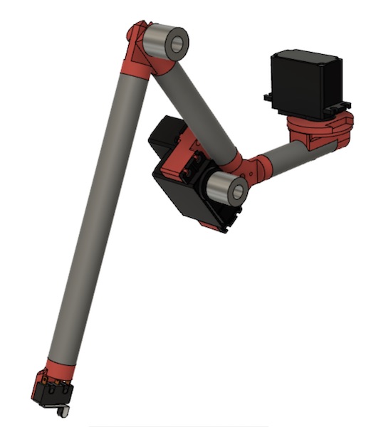
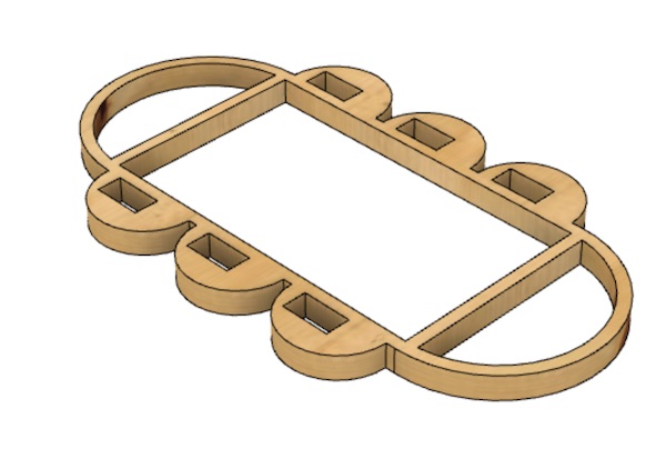
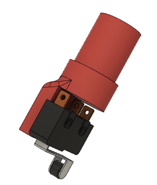
I took some time this week to build a little prototype of the dreamboat. Here it is in Fusion360:
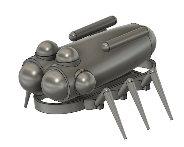
You’ll remember this is the little model I printed for the week 6 assignment. With the virus still wreaking havoc on academia, nothing is happening in the order we might have predicted back in January…
So now it’s final project time, and this week’s assignment is all about getting organised for that. The documentation for the final project will be more complete, with reflections on why I did what, and how I got to the details of the design.
Here I will document some of the trial-and-error learning I did on the journey to the final project.
Mechanical Design
Thinking about size. The beast should be about 30cm long and the core of it will probably weigh something like 1kg. That should be enough to start thinking about torques and strengths. I’ll also be limiting myself to materials I can work with easily in the lab and stuff I can buy quickly at the local hardware store. The final robot will therefore not look exactly like the CAD presented above, but I’ll try to keep as close to it as I can.
Leg Design
The leg dimensions were selected to give the robotic beast a shape similar to that of a crab or spider. The motivation is firstly esthetically pleasant, and secondly the geometries that Nature adopts are generally mechanically well founded. Since the weight is going to be of the order of 1kg, the mechanical design is quite straightforward. I’ll just use 15mm aluminum tubing for the legs, and I’ll CNC machine the frame out of MDF. I have the option of 3D-printing the joints, but since I just bought a 4th axis for my CNC machine, I might give that a go. Let’s see how time works out. The body will certainly be 3D printed, with its design adjusted to fit around the components I’ll have had to include in the frame.
Spec’ing the leg motors
The first real mechanical task is to decide how big the servo motors need to be which will support the weight of the machine. The shape of the legs is deliberate: the idea is to shorten the lever arms but also to load the leg tubes primarily in tension and compression, where they’re stronger, than in bending, which is what they would undergo were the legs straight out to the side.
There are three motors in the design of each leg. For simplicity and redundancy, I want to use the same servo motors throughout the machine. This will mean that two of the three motors will be somewhat overspecified, but the price tag isn’t so great that it will matter.
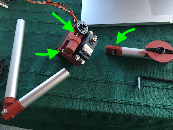
The leg assembly is shown below:
The worst case for loading in this arrangement is the knee or elbow joint, at the top of the picture, where the two long beams meet. The motor has to provide the torque to hold the two beams in any particular orientation. The balance of torques will look like this:
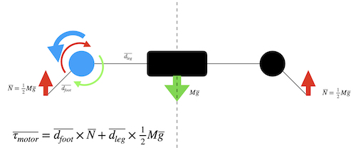
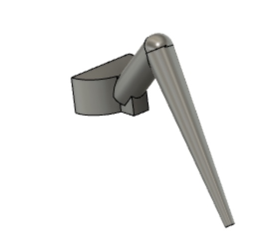
With dimensions dfoot=20cm, dleg=10cm, and M = 1kg, the total torque at the blue joint is 0.5kg x (7.5+15) = 11.5kgcm (weird unit, but it’s what the servo manufacturers seem to use). Because the robot will actually be supported on at three legs at all times (it will walk with an alternating tripod gait), the load will be some 30% less. The leg will furthermore be designed never to go flat, but rather always have a bend at the motor joint, which will reduce the torque further. It will therefore be sufficient to use a standard analog servo with a stall torque at 5V of 9 kgcm. FeeTech makes a relatively inexpensive motor that will meet these specs. There doesn’t seem to be a standalone datasheet available, but the description is on the web here. Conveniently there’s a GrabCAD model of this servo available in STL format:

Now that the motor has been selected, the CAD can proceed around it and the electronics, which I’ll describe in the following sections.
CAD
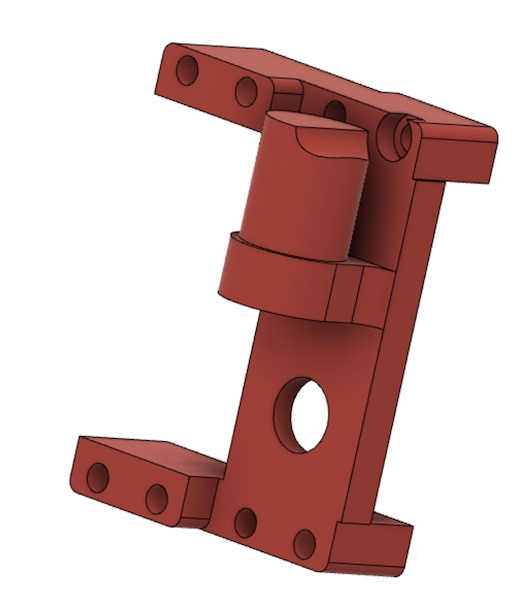
The legs are the first assembly to sort out. The dimensions and materials are selected, and the motors have been specified, so all that’s left is to put them together. Here’s what the CAD looks like:
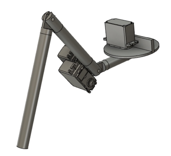
The first motor is fastened to the riser on the disk, which will be fastened to the rover’s main chassis frame. The first leg segment (called the femur) rotates around the axis of the motor shaft, with probably roller bearings between its top surface and the underside of the disk. The idea there is to carry the weight using structures which aren’t the motor itself.
The other two motors are mounted on the second leg segment (tibia). One of the motors drives the angle of the tibia relative to the femur directly through a shaft. There will be a bearing of some kind around that shaft to take the forces, so that the motor only has to deal with the torque. The second motor (of this pair, third overall) is also mounted at the inboard end of the tibia, with a belt out along the tibia to the “ankle” joint, where it actuates a pulley on a shaft to actuate the foot segment. There are two reasons for keeping the third motor inboard: to reduce the outboard weight and to improve the clearance between leg segments when assembled on the main chassis.
Once the geometry was settled and belts/pulleys ordered, the final shape of the knee and hip joints could be drawn up. Space had to be left for the shaft attachments of the servos. The final design will have to be revisited once the parts arrive and exact measurements can be made. It will probably also be necessary to tension the belt, so the final design may have to change again. For the moment, though, here is the state of play:
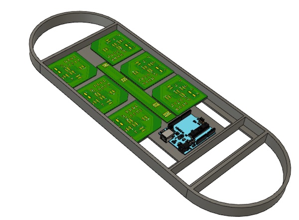
The chassis has to be large enough to spread out the legs and to accommodate the electronics boards that will control each of the leg units. The design of the boards is described in the next section, but the important part here is the overall dimensions. The boards, and Arduino Uno and a serial bus were assembled into a compact planar arrangement. The chassis was then built around those, lengthened a bit to spread out the legs for locomotion. A shelf around the inside of the frame provides an anchoring point for the circuit boards and strengthens the frame itself.
Manufacture
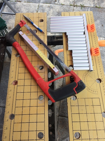
The long elements of the legs are made out of aluminum tubing, which was quickly acquired in the local hardware store. Some quick work with a carpenter’s rule, a pen, and a hacksaw produced all of the long tubular parts for the little beast.
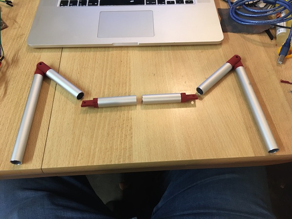
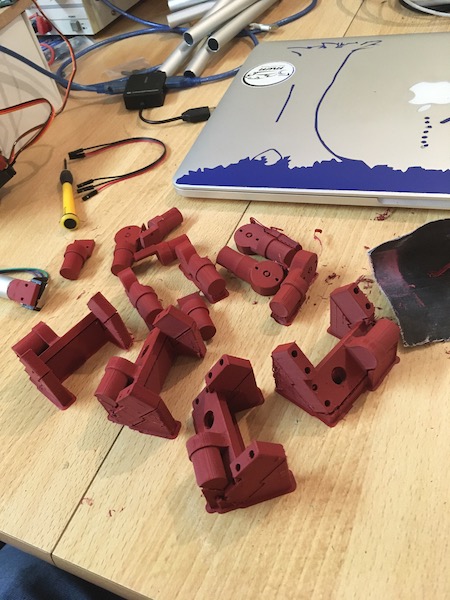
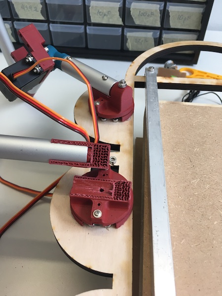
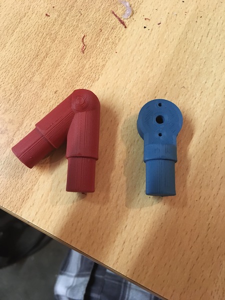
The joints were made on the 3D printer. I increased the fill percentage to 30%, set the parts on their sides to avoid creating shear planes perpendicular to the long axis of the parts, and used the gyroid fill pattern to give the parts a bit more strength. The joint parts are shown below with the aluminum tubes.
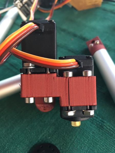
The servo motor holders for the legs are next.
After manufacturing the first two legs, a number of design flaws became apparent. The outer bracket over the servo motor was in the way, so I sawed that off. The hole through which the servo motor was to drive itself off the femur was only just big enough for the servo’s splined shaft, so that had to be drilled out, and there wasn’t enough room for the heads of the bolts (or nuts for that matter) fixing the top side of the servo motors. Then a discovered that the proximal knee element wasn’t fit for purpose either, as the femur fouled the lower end of the bracket on the distal part. The chopped off bit of outer bracket served nicely as a spacer, but I will have to redo these parts for the next round.
Some quick Fusion360 work later, and voilà:
Another problem appeared after assembly.
That problem will be fixed by changing the orientation of the part during printing, so that the layers cross the part diagonally instead of parallel to the shear forces.
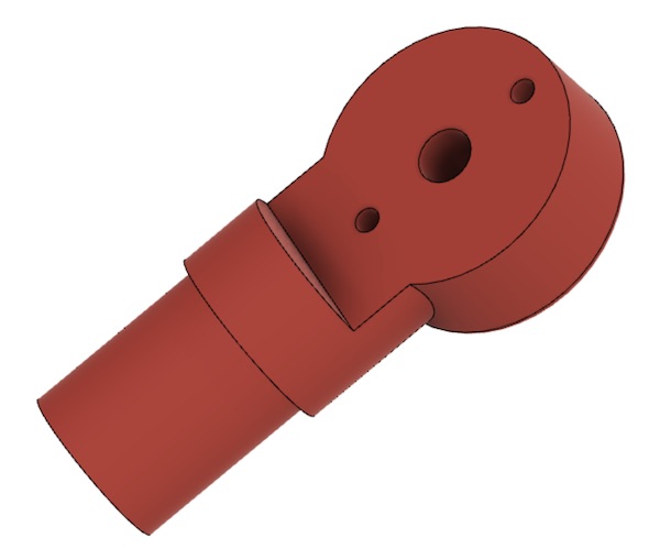
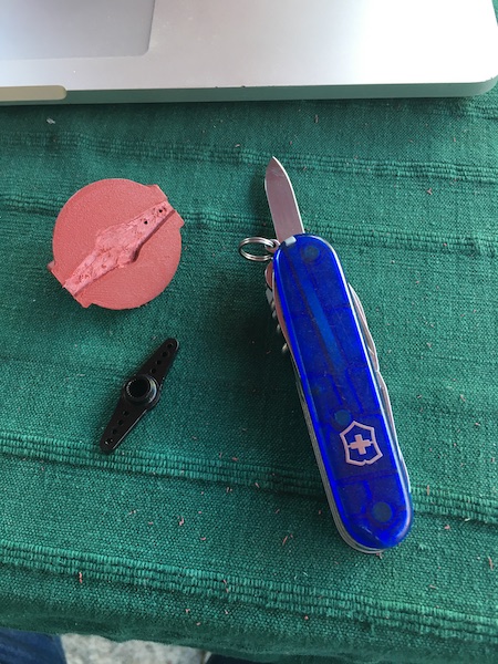
As the leg came together (and those design flaws showed themselves), I realised I had another incomplete bit of design in the shoulder joint. So armed with the experience from the previous flaws, I went back to Fusion to design an interface to connect the femur with a servo lever arm. This printed alright, but another lesson was learned - this time about allowing for the thickness of the 3D printer bead - so some careful, but rather brutal swiss army carving was necessary. On the first revision, I widened the gap by 0.4mm. Hopefully that will “just work.”
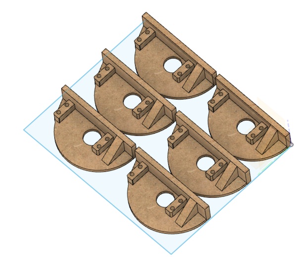
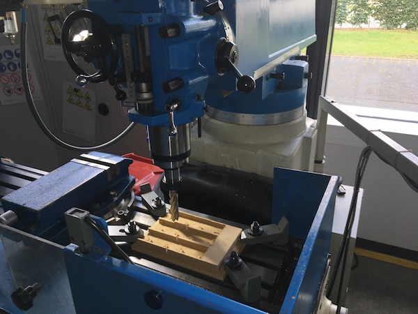
The final scapula unit also needed some tidying up, and then it was ready for milling. I put six of them on one block of MDF.
Before I sent them off to the Genmitsu, I commented out the Fusion360 incompatibility that homes the milling head of the Genmitsu to some odd place (see our week 5 group project for details. As before, I started by cutting air, and am I ever glad a did. This time the milling head went horizontally from the zero point at the bottom of the block to its starting point in the middle of the block, and THEN rose to the clearance height! I dug into the g-code and added a line to the top:
G0 Z35
I wasn’t sure what speeds to cut MDF with, so I googled it, and didn’t the Fablab Speed and Feeds Calculator come up as the first page! The largest tool I have for my little mill is a 3.175mm (1/8 in), 2-flute flat end mill. The table in the website suggested 650 feet/min and a chipload of 0.005 in. I added those in and hit calculate, which suggested the following settings:
| Setting | Value (std) | (metric) |
|---|---|---|
| Spindle speed | 19863 rpm | |
| XY feed rate | 199 in/min | 5055 mm/min |
| Plunge rate | 99.5 in/min | 2527 mm/min |
| Stepover | 0.05625 in | 1.43 mm |
| Stepdown | 0.0625 in | 1.5 mm |
I don’t actually know how fast my little mill spins (Genmitsu just use ‰), but I’m fairly sure it’s nowhere near 20000 rpm. I’m also fairly unhappy thinking about it trying to drive anything at 5000 mm/min. So I took an (newly) educated guess:
| Setting | Value (std) | (metric) |
|---|---|---|
| Spindle speed | 1000 ‰ | |
| XY feed rate | 39 in/min | 1000 mm/min |
| Plunge rate | 39 in/min | |
| Stepover | 0.06 in | 1.5 mm |
| Stepdown | 0.04 in | 1 mm |
It’s going to be a while…
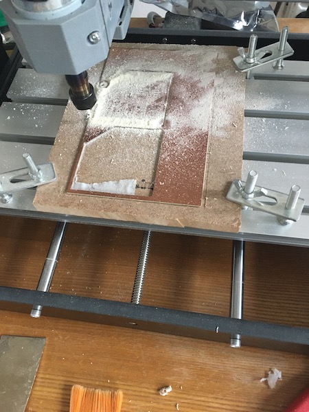
We’d never get anywhere if it weren’t for steps backward. Sigh. Obviously sensing the deadline approaching, the Genmitsu packed up overnight and didn’t finish the job. I have neither photographs nor acoustic recordings of the blue air that surrounded the hapless machine the next morning. In the end, it was probably a good thing that it gave up, because although I tried to finish the job on the mill in my lab:
the MDF didn’t survive the operation. The material just couldn’t take the machinining and delaminated everywhere, especially as I tried to prise the finished parts off the underlying bed to which they’d been glued with carpet tape. I’ll spare you the gory details, but suffice it to say that a new solution was needed quickly.
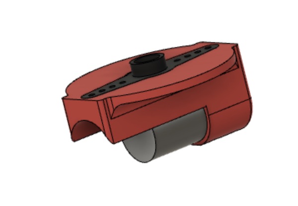
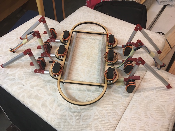
The solution came in the form of a laser cutter in Xanten. Daniele’s very kind offer also solved the manufacture of the frame problem. He had some 10mm plywood available, so I modified my CAD to combine the frame with the scapula elements:
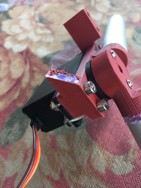
That came back from the laser printer beautifully cut. It did feel a little fragile, but the quick addition of two aluminium bars to its underside (which also serve to carry the electronics board - more on that later) made for a sturdy little beast. Here she is after the addition of motors and leg assemblies:
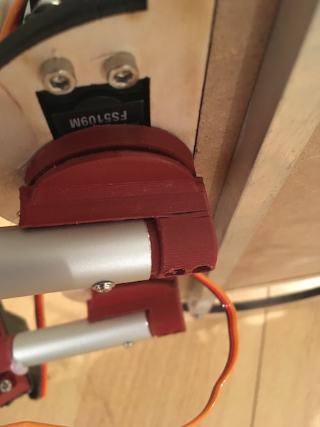
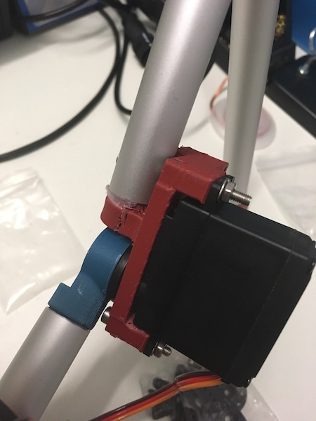
The change in the mounting arrangement for the motors meant that I had to design a little spacer to mount below the plywood, on which the leg shoulder piece could turn. That needed a little cutout for the two bolts fastening the motor in place. I 3D printed six of these and glued them in place.
![]()
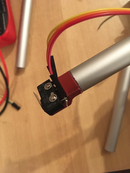
The beast is to be provided with information about whether or not its legs have made contact with the ground. For this the intent is to use a microswitch at the tip of the leg. A finger part was therefore designed and printed, to which the microswitch was attached.
Second Iteration
There were several lessons learned in the first iteration. Not relying on MDF for structural strength was an important one. Recognising that the fault lines in 3D printed plastic parts can lead to unexpected weaknesses was another. Even after recognising that in the first iteration and correcting for it by turning the part 45°, I still didn’t completely solve the problem. The part no longer split along the bolt holes, but instead now there was a shear plane out along one of the motor brackets. In the final version, I’ll have to think much more carefully about the orientation of the shear planes and possibly about the infill pattern.
It became apparent also that the third servo motor was too much for the code I had running on the leg boards (described below), so I opted to remove them from the design for now. I’ve left the knee parts with their additional brackets (which break off anyway), but I’ve removed the belt and pulleys, and redesigned the ankle to be rigid. As I get a better handle on the servo motors (may have to use a more powerful chip, which will require a complete redesign of the electronics), I’ll revisit the third motor mechanics on the legs. The new CAD looks like this:
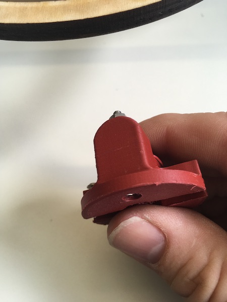
The shoulder was another weak spot that needed reworking. In one of the units, a crack has begun to appear between the print layers:
This hasn’t showed up yet in the other shoulder parts, so I’m not going to worry about it for now, but once the robot is walking, I’ll have to monitor that weak spot. The bigger problem with the shoulder parts was the way they were fastened to the servo lever arm. The original design had the servo arm parallel to the femur, which meant it could only be fastened with screws at one end. Initially the intent was for a press fit to hold the arm in place, but that failed fairly quickly. I tried hot glue, but that also failed, so it was back to the drawing board.

The solution I’m trying now is to rotate the arm slot 90° so that I can mount the RP part on the servo arm with screws at either end. I’ve made the slot in the shoulder part deeper to fully enclose the servo arm. I may need a small spacer to bring it back out so that the machine screw holding the arm to the servo gear can be tightened without jamming the shoulder part against the spacer on the scapula.
Adventures in Cracking
As I proceeded with testing (making the machine do push-ups), several other weaknesses began to appear. The one in the shoulder piece turned into a full-on failure, which I initially fixed with a bolt.
That worked for one leg, but then next one gave out:

Once the part is cracked in two, it becomes clear that the wall thickness and low-density infill material just wasn’t enough to carry the load.
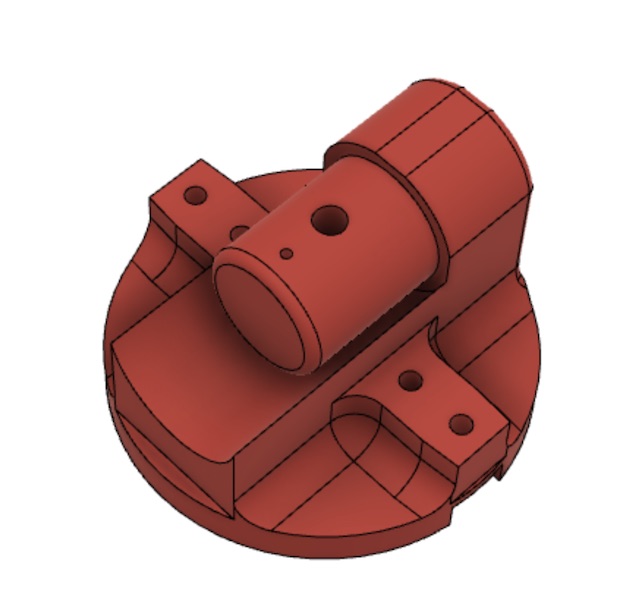
On the next design iteration, I made a feature out of the bolt, and added it into the Fusion360 model. I also thickened the walls during the print job. The new settings for the print job look like this:
| Setting | Value | (unit) |
|---|---|---|
| Layer height | 0.2 | mm |
| Initial layer height | 0.2 | mm |
| Wall thickness | 3 | mm |
| Top/Bottom thickness | 3 | mm |
| Infill density | 45 | % |
| Infill pattern | Cubic | |
| Printing temperature | 200 | °C |
| Build plate temperature | 50 | °C |
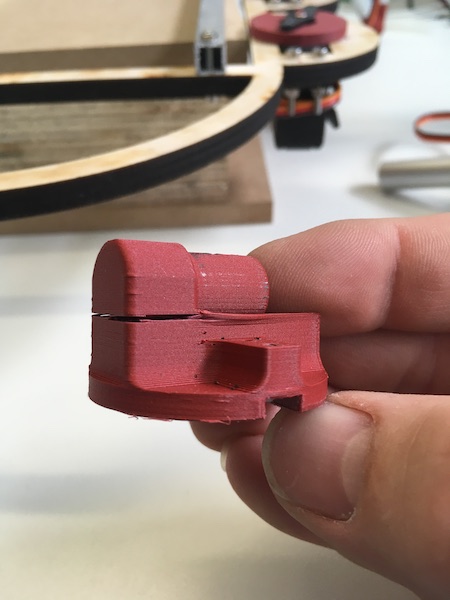
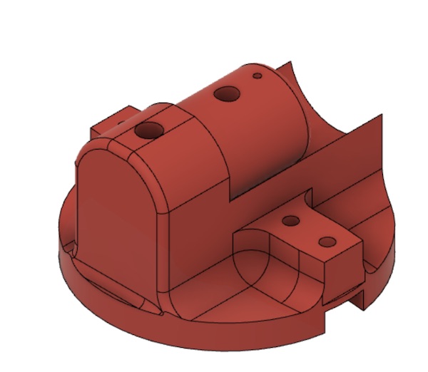
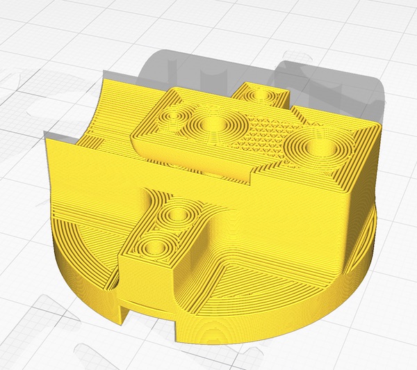
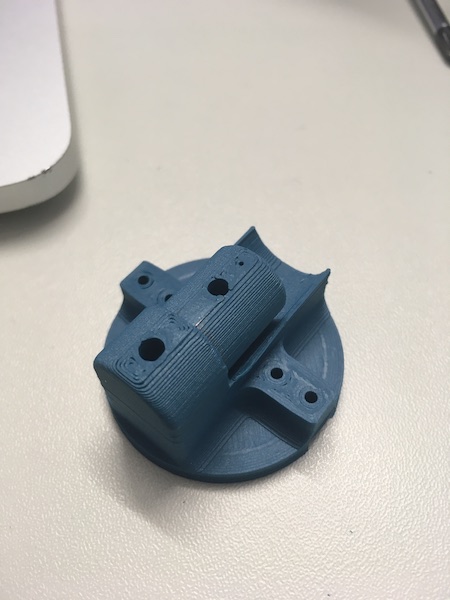
The extra hole through the larger end of the part generated more structural strength there. What had been lightweight infill was now wall thickness. Below are the CAD of the new part, a cross section through the simulated print job, and the part after printing (note I ran out of red PLA). What’s not obvious from the picture is that the new part weighs nearly double what the old one did.
I had a similar problem with the elbow joint, which I fixed by rotating the part 90° around its long axis and printing with the higher wall thickness. Here’s the problem and its solution, alongside the solution to the ankle cracking identified earlier.

Finally I also had to redo the knee elements, always for the same reason.
The final 3D Printer settings were as follows:
| Setting | Value |
|---|---|
| Quality: Layer Height | 0.2mm |
| Quality: Initial Layer Height | 0.2mm |
| Shell:Wall thickness | 3mm |
| Shell:Top/bottom thickness | 3mm |
| Infill: Density | 45% |
| Infill: Line Distance | 1mm |
| Infill: Pattern | Cubic |
| Material: Print Temp | 200°C |
| Speed | Build Plate Temp |
| Support: Structure | Normal |
| Support: Placement | Everywhere |
| Support: Overhang angle | 45° |
| Support: Density | 20% |
Third iteration
The whole machine is pretty wobbly on its feet, in particular as the parts all begin to move. The plywood frame flexes at each motor, the shoulder rotates around the axis of the servo motor arm, the various leg parts all twist in their end joints, and the motors aren’t strong enough to lift the weight properly. To make a functional little beast out of this prototype will require a complete rethink of the joint designs. Four-bar linkages, bearings, belts and gearboxes will be the next steps. That will be for later, though.
Control Electronics
No robot is complete without an electronic nervous system. My little rover is no exception! The design philosphy is “distributed control” with a biomimetic approach to keep it simple.
System Design
The overall architecture consists of a control board for each of the legs, connected via a serial bus to an Arduino Nano, which coordinates the motion of the legs and communicate via a radio link with a computer.
Leg Board Design
The development of the first leg is all described in the Week 12 assignment.
A second leg
The first of the parts for the second leg are slowly appearing on the machines…
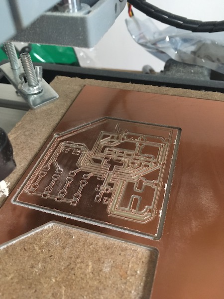
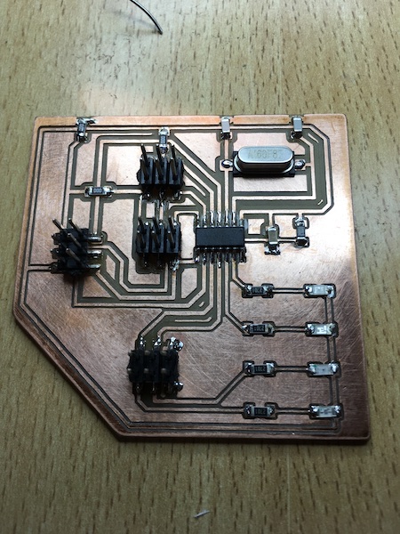
The board cleaned up fine with a bit of emory paper. This time I remembered to clean out the traces with a probe before plugging it in. The board more or less stuffed itself. This time with no band aids.
Burning the fuses went well, as did the first LED flashing program:
I then wired up another microswitch and connected it and three servos to the new board. I found a USB power cable and used that to power the second board. The result is lots of lights and action!
More legs
I repeated the process twice more on my little Genmitsu, and Daniele made two more boards on his mill as well. The stuffing of the boards didn’t always go completely according to plan and I ended up with a couple of “Frankenboards”, where I had to make replacement traces out of bits of stranded wire or add full-on jumpers.
I had several issues with shorts across the various PCBs, either because of tiny specks of swarf from the milling and sanding process, or because of bits of stranded wire leftover from the frankenboarding. Once those were all cleared away under the microscope, the boards generally worked. Flashing was not usually a problem, and I could usually get them to fire right up with the “blink” sketch.
To keep everything organised, I stuck the PCBs to a piece of MDF dimensioned exactly to fit in the plywood frame. As the PCBs were all single sided, I just used carpet tape to hold them in place. This had the advantage that replacement was straightforward when necessary.
I added a breadboard to the MDF as well, to which I could connect the Arduino Nano brains of the outfit. Eventually, I’ll replace that as well with a board I’ve made myself.
Setback: RIP Ugly Duckling
At some point, for a reason I never did understand, my Ugly Duckling FabISP board gave up the ghost and ceased working. I tried to make a new FabISP to replace it, but that also failed, this time at the fuse burning stage (see the “how to brick a FabISP” section in week 05). So I gave up and turned to an Arduino Uno I had lying around to become the new ISP board. I’ll make a new FabISP later and try to flash the fuses more carefully this time.
Spinal column
It was inconvenient, to say the least, to continuously plug and unplug the four ISP wires, Vcc and ground from each of the boards, since they each had to be isolated electrically from all of the others in order to be programmed. In the end, some of the tabs started giving way and the pin headers came away from the PCB, with their pads still intact. It was therefore time to stop and work out a better solution.
The ground connection was straightforward, since I could just solder jumpers from board to board, and added two wires at the ends nearest the breadboard, so that the leg boards and Nano were all grounded together. During the programming attempts, it became obvious that all of the boards had to be switched off except the one being programmed, and that all ISP headers had to be removed once the programming was complete. Repeated pulling wires from the headers resulted as described above in broken headers and in wires coming out of the sockets at their ends. My fat fingers are I guess not designed for this kind of thing.
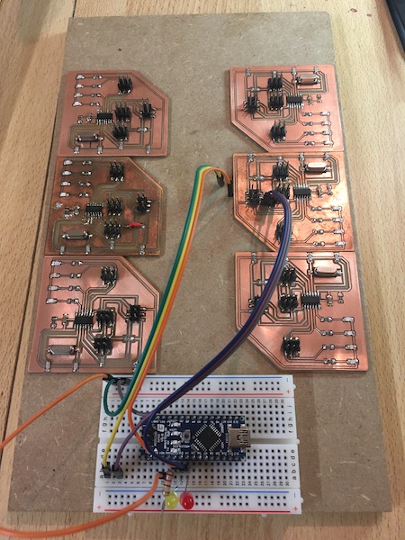
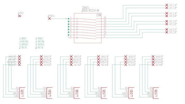
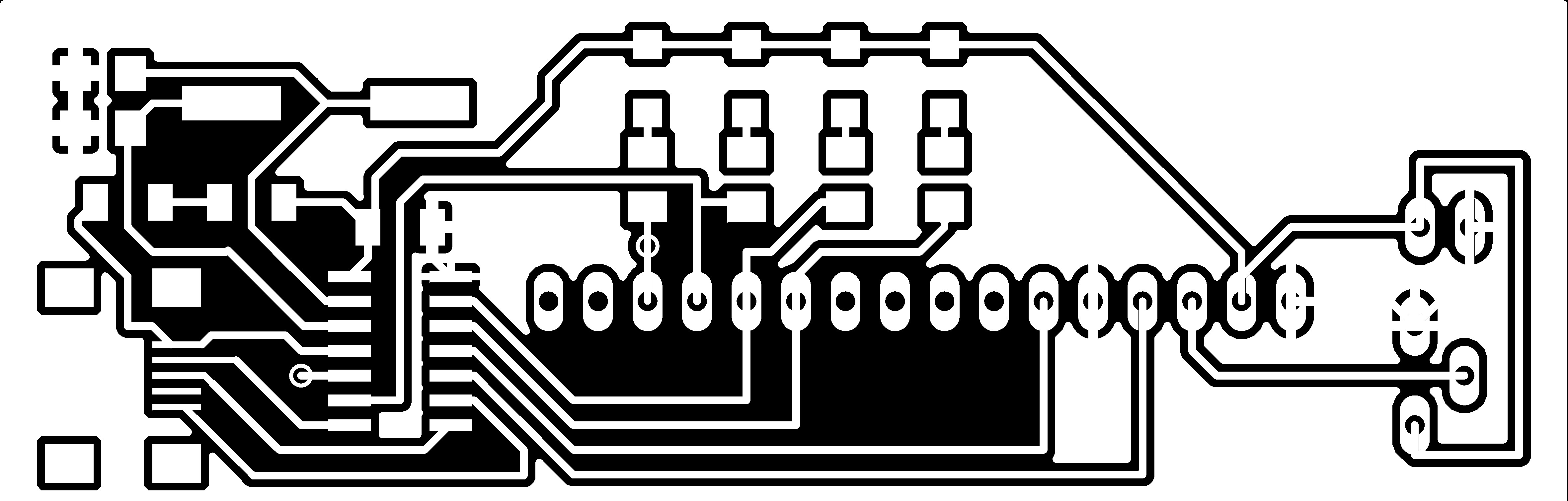
So I decided on a more robust solution which makes use of USB-A sockets for the four pins of the ISP header, and independent Vcc run through an 8-channel PCB switch bank. I made a simple circuit board in Eagle:
The Eagle files are here and here.
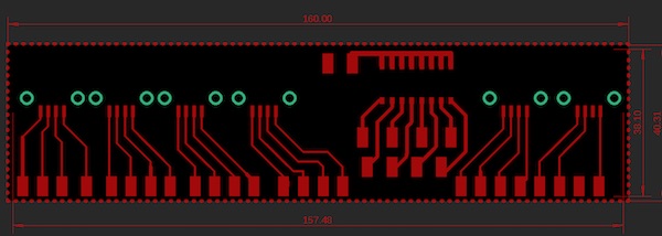
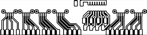
I then followed the instructions I’d made for myself earlier in this document, and milled them out on the Genmitsu using the following image files (which were turned 90 degrees in Preview so that I could cut along the long edge of the board blank.)

It didn’t really matter which pin of the USB-A socket was connected to which pin of the ISP header, as long as the cable I designed to connect the USB-plug to the Arduino was also wired accordingly, but I did want to avoid any problems with accidentally connecting a real USB cable to the sockets, so I made sure that RST would never be connected to GND. I connected the SCK pin to what would be GND in the USB standard, and MOSI/MISO to the other two, as shown above.
I soldered leads between each of the breakout pads on the new PCB and the base of the corresponding pin headers on each of the leg boards. I had to juggle soldering irons since the big copper wires sucked all of the heat out of the tiny iron I used for the boards, but the big iron was just too clumsy for the precision soldering on the boards. I then cleaned up the cabling, and here is the result:
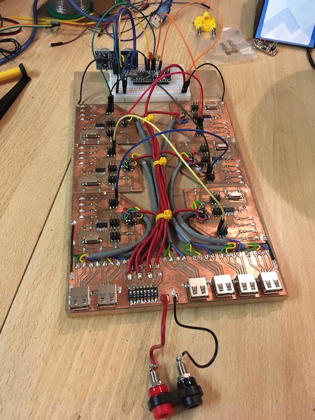
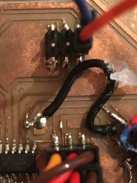
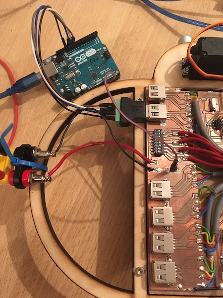
The USB-ISP cable then connects the four pins to the Arduino Uno in the usual way, as shown in the photo below. Notice the additional ground wire that connects the Uno to the robot. There is a ground path through the power supply and the real USB cable to the Uno from the computer, but it turned out not be stable enough for the programming, so I soldered the pair of pin headers to the copper pour of the power distribution board.
The result is that it now takes 2 minutes to reprogram all of the leg boards, instead of the 4-5 hours of electric debugging and soldering that was the name of the game while I was pulling wires and plugging them back in.
Upgrade for Power
During initial testing, there were often unpredictable resets or the motors would fail to stay in sync, which resulted in collisions between them, or in the robot slowly collapsing over time. After some discussion, we suspected that the current delivery by the benchtop power supply might not be sufficient during peak demand by the servos to maintain the 5V supply to all of the boards, and that they were therefore resetting themselves.
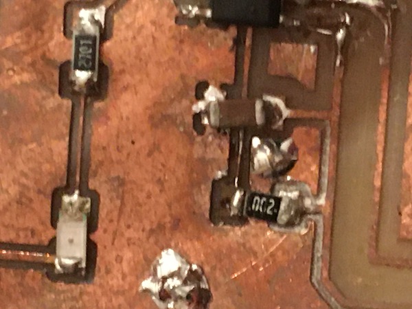
The first part of the solution was to add a big 100 uF capacitor across the servo power supply, negative to GND and positive to the Vcc (5V). This was to provide a buffer during peak demand times to keep the servo voltage at 5V when the power supply couldn’t deliver. In experimentation after the modification, though I made no quantitative measurements, it really felt as though the servos had more available mechanical power.
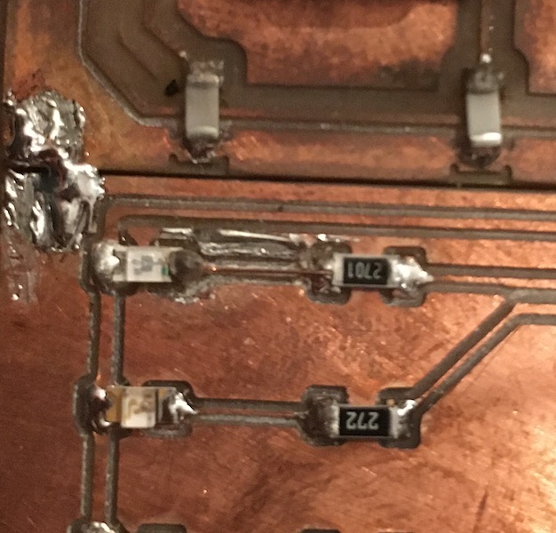
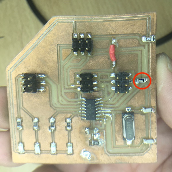
The second part of the solution was to redesign the power provision and isolate the servos and chips. This was made relatively easy by the serendipitous design of the leg boards, which included a zero-Ohm resistor bridge across a ground trace to power the servo motors (circled in red in the image below). Removing this jumper isolated the servo positive rail from the rest of the board.
With the isolation completed on each of the PCBs, I then had to build a new power distribution network to supply the two sides of the circuit. I unsoldered the banana plug positive lead from the foot board and replaced it with a pin header so that 5V power could be brought in from the computer USB port via the Arduino Uno I’ve been using as an ISP to program the AtTiny chips. The banana plug lead was then connected to a 12 gauge wire which ran the length of the robot to a screw terminal near the front. Each of the servo lines then had a 12 gauge wire of its own soldered to the same pin as the capacitor and run to the forward screw terminal.
I also took the opportunity to replace the Arduino Nano board that had been controlling the robot with the swan board I made myself. I stuck it to the breadboard with double-sided tape and reorganised the serial bus to reestablish the daisy chain over the leg boards.
The newly rewired robot looks like this:
Programming
Programming started where the fuse burning ended. A first go with a modified Arduino “Blink” example confirmed that all four LEDs worked ok (also reminded me how to use a for loop in Arduino).
The sketch is available here.
Initial Attempts
To get two motors going, I used the PWMServo_v2 library. A few adjustments were required to use that library with the ATtiny84. The mods were provided by “pxgator” on the Arduino forum. Basically it’s just a question of adding the following code to the PWMServo.h file:
#elif defined(__AVR_ATtiny84__)
 #define SERVO_PIN_A 6
 #define SERVO_PIN_B 5
That allowed me to use two of the servos, as shown here (you have to look carefully to see the dial turning on the second servo).
The sketch is here.
Driving Three Servos
My first design included three servos in each leg. I managed to find some code online which made that possible, and the development is described in my report for Week 12.
Feedback control
The objective with each arm/leg is to have it do a stereotypical movement which is interrupted by contact with the ground. Usually in hexapedal robots, one goes through complicated inverse kinematics to work out how to code the steppers to deliver the end-effectors to specific places in 3D space. In this design, I’m looking to operate more like a simple animal. The foot goes down until it hits the ground and reaches a given level of ground contact force, then the animal moves forward.
I gutted Tyler’s code but kept the servo control subroutines and his approach of using the millisecond timer and switch statement as an event driver. In the leg motion I am trying to reproduce, there are four stages in each stride: lift up, surge forward, set down, surge astern. The first, second and fourth of these are simple movements that simply step a position variable one way or the other until a limit is reached, at which point the stride phase is augmented and the next phase starts on the next iteration of the loop. When the stride phase counter reaches 3, it is reset to zero and the pattern starts again. The third phase is different in that it has to monitor the state of the microswitch. If the switch is pressed, the code simply doesn’t move the motor and a new lower limit is set. That lower limit is reset to its original value when the leg is lifted again in stage 1.
The sketch is here
The motion is shown in the video below. The left hand servo moves the leg in surge, while the right hand one moves it in heave. As the leg moves down (the lever comes towards the camera), I’ve simulated ground contact with the microswitch. Note the heave motor then stops and starts back up from that position once the surge movement is completed. On the next cycle it carries on until the switch is clicked or the resting limit is reached.
Central coordination
The goal is an alternating tripod gait. That means that three legs remain in contact with the ground while the other three are lifted, moved forward, and put back on the ground. Once the weight is distributed among the six legs again, the second triple is lifted and moved forward. In this way, the rover remains stable at all times. The gait is inspired by terrestrial insects like cockroaches.
In my little rover, the tripods are designated “red” and “yellow”, for the colours of the LEDs I plugged into the Arduino Nano that coordinates the motion. Each of the legs begins its stereotypical motion when one of the input pins (pin 9) goes low. In principle then, all I needed to do was wire legs FR, ML and BR to the “red” pin on the Nano, and FL, MR, BL to the “yellow” one, then wait for the pin to go low before starting the motion.
Second Prototype
The first version of the software architecture simply had the legs responding to a low signal on their input pin. The driving Nano sent that low from one of its output pins along one bus to boards 1,3,5 and from a different output pin along a different bus to boards 2,4,6.
Now in this version, the controlling board (now also a self-made board - the Swan Board from week 09) now sends a serial sentence along a single bus to all boards at once. Each of the boards reads the sentence, decides if the message is for it, and if so, follows the command. If the message is intended for another board, it is simply ignored.
Sofware Serial Communications
The AtTiny boards do not have serial ports built in, but there is a handy library called SoftwareSerial which does the trick nicely. The controller (swan board) uses the following sketch to send:
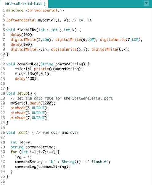
The first two lines set up the Software Serial library and create an object. The subroutine flashLEDs flashes the LEDs according to a binary pattern on the three integer parameters and, importantly, introduces some delays (that will come up again later in the story). The commandLeg subroutine puts the command out onto the serial bus, flashes some LEDs, and again puts some delay into the system. Next the built-in setup subroutine initialises the Software Serial communication and sets up the LED pins. Finally the loop sends the message to the serial bus. The message is always formatted thus:
"Nx y**** zzz"
where x is the leg number identifier, which is one of: - (0) no legs (eg for sensor comms) - (1-6) for each of the legs individually, or - (7) all legs should respond simultaneously
y* is one of: - *flash - just flash the LEDs - sweep - move the leg forward or aft - heave - move the leg up or down
Note the **** characters are not important, just that there are exactly four of them.
and zzz is the argument (angle) of the movement command (argument of ‘flash’ is 0).
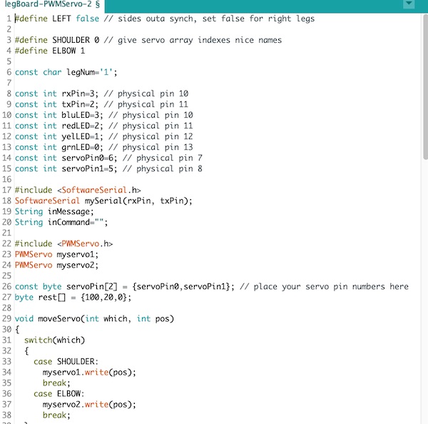
Each of the legs uses the following sketch to listen for commands.

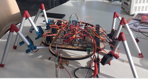
Here is the system in action.
If you watch the LEDs on the swan board at the front of the beast, you’ll see the binary pattern indicating which leg is being activated. Blue is the most significant bit, green the middle, and yellow the least significant. Each of the legs then deciphers the message and flashes red when it’s been received, then flashes yellow if the message was intended for itself.
Leg Movement
The leg servos offer two movements: the shoulder provides a sweep fore and aft, and the elbow heaves the leg up and down. The leg board sketch is set up to read the software serial commands, decipher them, and then action the leg servos or LEDs accordingly.
The code is available for download here.
The sketch is in x parts. The header includes some libraries and defines a series of constants, the most important of which is the legNum. This is the identifier each board’s sketch looks for in the serial commands to identify whether the message it’s deciphered is indeed intended for it.
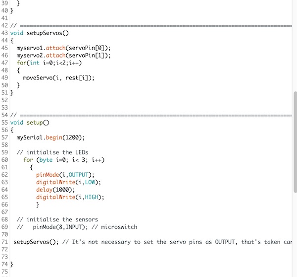
The next block is a pair of subroutines to control the motion of the servos. In setupServos(), the resting position of the servos is also set.
The setup subroutine initialises the Software Serial communication, sets the LED pins for output and flashes them in sequence, then initialises the servos to the resting position.
The loop subroutine has two parts. The first reads and deciphers the serial message, flashing the red LED to indicate the message has been received (note the blue LED flashes on its own due to the serial signal on the bus). The second part decides what to do with the command. The identifier (2nd character of the string) is first checked, then the first letter of the movement word is extracted, and the appropriate servo is called to move to the angle indicated in the argument. The green and yellow LEDs are flashed in the following pattern:
- green: Sweep
- yellow: Heave
- both: Flash
In the ‘sweep’ command section, the left side legs (4,5,6) are programmed to sweep in the opposite direction from the right side ones.
Standing
With the new power distribution network and software serial communications, it was time to get moving. First things first, though. Step 1 - stand up.
To stand, the bird board simply sent the command
"N7 heave 120"
to make all of the legs go from limp (upper frame, below) to energised (lower frame, below).
Push-ups and Swing Dancing
As a first test of the new dynamic performance, I had the robot do push-ups. This was a simple addition to the bird board code to give the commands (pseudocode):
"N7 heave 120"
delay(1000)
"N7 heave 140"
delay(1000)
The robot had no trouble with the exercise, as is shown in the video below:
The second test of the new servo power was to have the robot swing back and forth. In this case the commands were:
"N7 swing 100"
delay(1000)
"N7 swing 80"
delay(1000)
The movement with all six legs at once can be seen in the video below, though the robot is supported on some blocks, so it is not actually dancing. Its best moves all happened, as with all great dancers, off camera!
Walking one leg at a time
The objective was to build a robot that could walk on six legs. To achieve forward movement, the requirement was that the legs swing themselves back (and therefore the body forward), then pick themselves up one by one and swing themselves back forward before heaving back down to the standing position. The commands were:
"N7 swing 100"
delay(1000)
for (i=1;i<7;i++) {
    "Ni heave 140"
    delay(500)
    "Ni swing 80"
    delay(500)
    "Ni heave 120"
    }
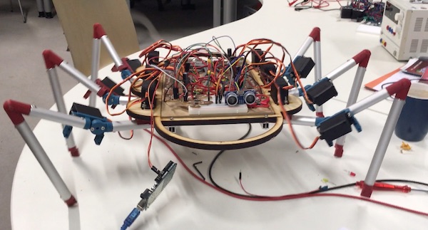
Though not particularly well balanced on its six legs, whose 3D-printed parts were all slowly failing at different rates, the robot walked successfully forward. In the video below, it has just broken one of its legs by tangling it with the back leg in some random errors during the startup sequence. It soldiers on nonetheless, as if determined to show the world what it can do!
Feedback Stopping
The last step for my final project was about having the robot respond to some external stimulus. For this purpose, I added an ultrasonic sensor to the front of the machine and connected it to the bird board via two of the ISP header pins (which were also the green and yellow LED pins). The ultrasound device, HC-SR04, has four pins: VCC, GND, Trigger and Echo.
There was a major hiccup with the addition of the ultrasonic sensor. The robot could walk perfectly fine before it was connected, but as soon as we added the subroutines which depended on microsecond timing, the rest of the software serial based communication seemed to fall apart. That led us to believe that something about the ultrasonic sensor was causing the problem.
After much debate and experimentation, we realised that the problem was not the ultrasonic sensor itself, but rather that I had turned off the flashLEDs subroutine on the swan board since their pins were now also being used to communicate with the ultrasonic sensor. The issue was that the delays that had been built into that subroutine allowed the legs to complete their movements before the next serial message arrived.
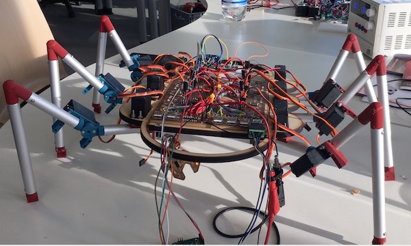
The final walking demonstration is shown in the video below, including the stopping due to the detection of an obstacle (note the blue LED on the swan board lights when the hand is detected). During stopping the robot doesn’t swing its legs. Instead it only heaves them, as if jogging in place.
And with that, I’m going to declare victory and go home. It’s been a fun ride. I’m looking forward to tidying up the mechanical elements a bit before presentation day in January so that it walks a bit more evenly. I’ll also tidy up the wiring and replace the failing 3D printed parts. I’ve learned a lot and I’ll look forward to introducing my little beast to the world in Montreal next summer.
Epilogue
After the official ok from my local and global evaluators, I carried on improving the robot.
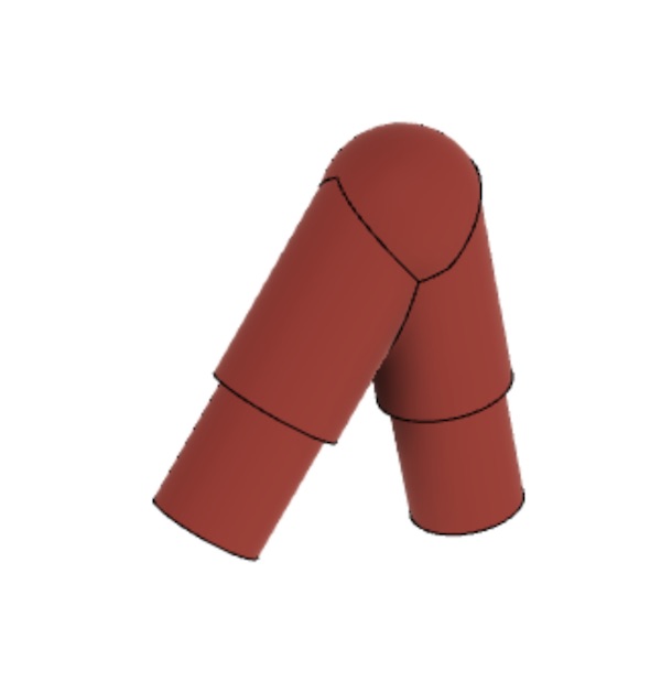
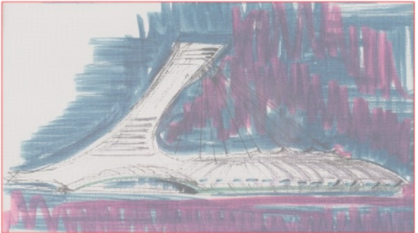
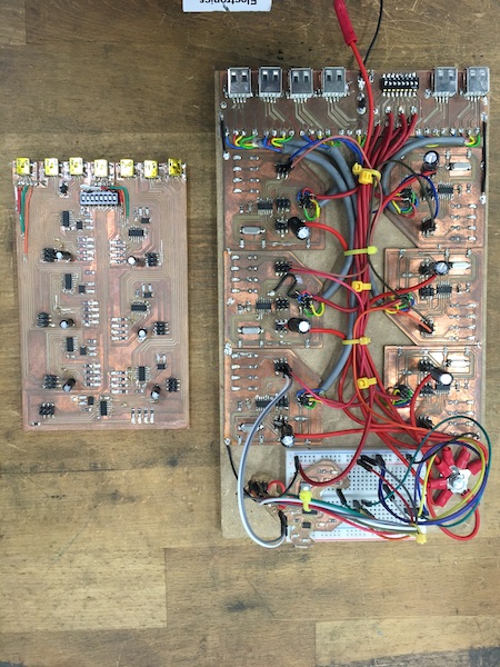
I made a decorative shell and a new motherboard.
The shell was inspired by the Olympic Stadium in Montreal.

Connecting the motherboard:
| Line | Cable | USB Mini | AtTiny | Arduino Uno |
|---|---|---|---|---|
| GND | Pin 14 | GND | ||
| MOSI | WHT | Pin 2 | Pin 7 | Pin D11 |
| Vcc | Pin 1 | Vcc | ||
| MISO | BLU | Pin 3 | Pin 8 | Pin D12 |
| SCK | BLK | Pin 4 | Pin 9 | Pin D13 |
| RST | BRN | Pin 1 | Pin 4 | Pin D10 |
Where the USB pins are counted from the left looking into the socket.
This is a map of the pins on the AtTiny84, according to how the Arduino IDE labels them:
| Physical Pin | Arduino Label | Brain Board | Leg Board |
|---|---|---|---|
| 1 | +5V | +5V | +5V |
| 2 | CLK | CLK | |
| 3 | CLK | CLK | |
| 4 | 1 | RST | RST |
| 5 | 2 | ISP 2 | HDRS 6 |
| 6 | 3 | ISP 4 | HDRS 5 |
| 7 | 4 | ISP 6 | |
| 8 | 5 | ||
| 9 | 6 | ||
| 10 | 7 | GRN | GRN RX EFF |
| 11 | 8 | YEL | YEL TX AFF |
| 12 | 9 | RED RX AFF | RED |
| 13 | 10 | BLU TX EFF | BLU |
| 14 | GND | GND | GND |
With the new motherboard came the opportunity to improve communications with the robot. I designed a new board to run a 16x2 digital display. Again based around the AtTiny84.
The microcontroller was connected via the SoftwareSerial network to the rest of the robot databus, and was programmed to respond to the commandString as if it were leg #8.