16. Moulding and casting
In previous years, this is where my FabAcademy adventure came to a shuddering halt. My own teaching commitments would take over my life about half way into our summer term, and I’d have to let go. This year, thanks to the quiet created by the lockdown, I’ve had more time to dedicate to this task and I’ve managed to get a little bit further…
A Maypole for the Campus
The task is to design and draw a 3D object to mould, then cast. I have had a project on the backburner for a while to make a maypole for the university campus. Maypoles have a long tradition in this part of the world, where they are often decorated with colours and carvings. They’re a symbol for the rebirth of spring, and in this region they were often left by a suiter at his best girls’ home, and because this is Germany, along with the kiss he’d get from the girl (if she liked the tree) at the end of the month, he’d get a cake from her mother and a case of beer from her father!

Fancy German maypoles, in particular in Bavaria, are often decorated with wooden carvings attached to the pole to tell some local stories. For our international campus, I opted to carve the stories into the pole itself, following the ancient British tradition or indeed the North American native totem pole.
The intent had been to errect it this spring on the square before the engineering buildings, where the Christmas tree usually goes. The pandemic put paid to that unfortunately.
A Miniature to Cast
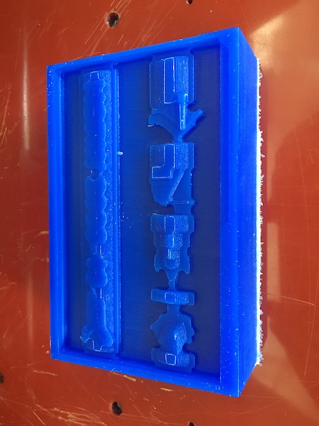
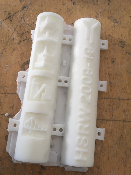
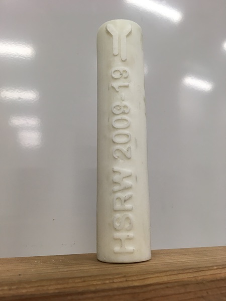
Instead, I’ve decided to make a miniature for this year and we’ll carve and erect the full-size one next spring. Here is the miniature, fit to the size of the blue block of wax we were given in the lab.
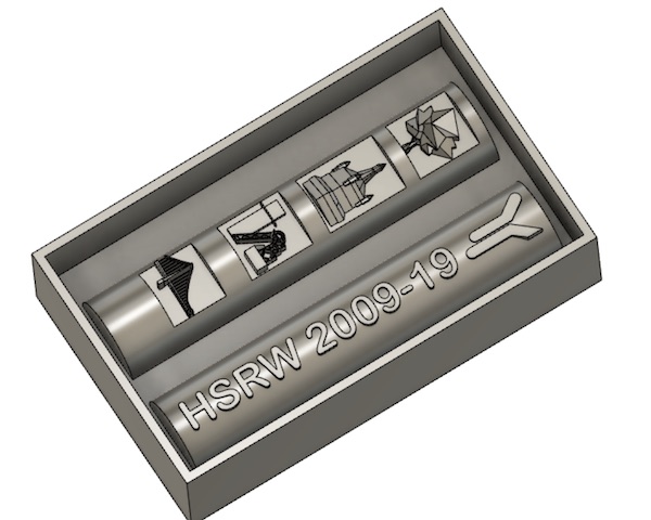
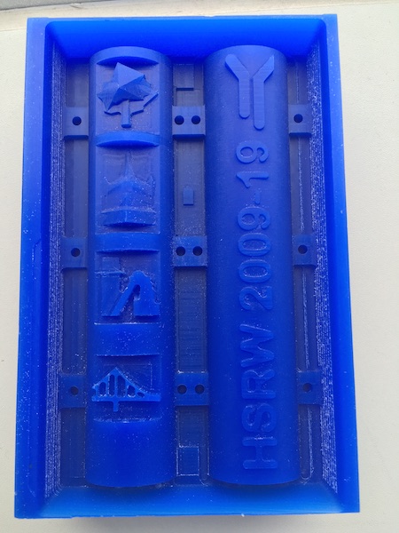
Eventually the pole will tell stories, but for now it just celebrates the university’s first ten years. This section is the base of the pole (it will have two sections when it is erected). One side is just the University’s “rivers” logo and the ten year dates, while the other side tells the story of our campuses. At the bottom is the suspension bridge at Emmerich, where we had our first campus from 2009-2012. The next box represents the RAG mine shaft building in Kamp-Lintfort, where our smaller campus is located. The third box up is a model of the Schwanenburg (Swan Castle) which rises over Cleves, where the main campus is located. The tree at the top of the pole section was selected to celebrate the University’s ten year anniversary in 2019.
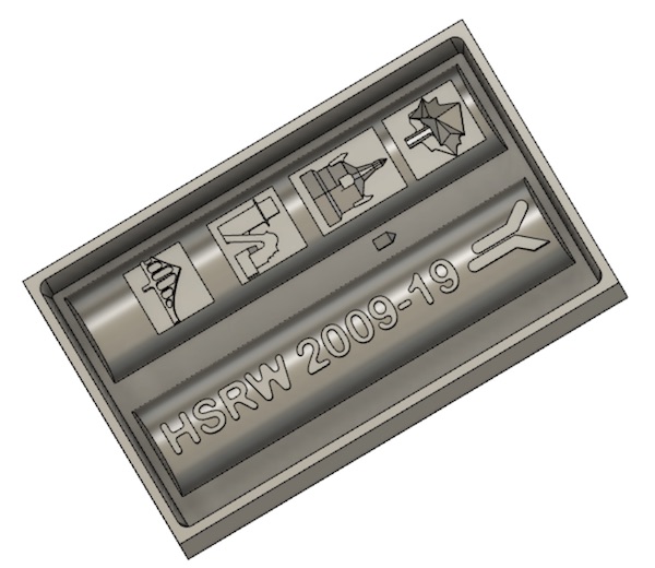
The model above is far too detailed for the small prototype I’m planning to cast for this week’s assignment. So intead, I simplified the design significantly, knocking details out everywhere while trying to maintain the essence of each of the panels. The result looks like this:
3D CAM
Clearance Strategies
Fusion360 has a set of preprepared strategies one can choose to clear the block material away from the model parts. The “adaptive clearing” strategy worked well to rough out the model. After that, it got more difficult.
Tool and Holder Collisions
I had modelled the tools and the holder of my mill, and experimented with the strategy settings to find that the “Trimmed” setting was most reliable, and that I could use clearances of 0.1mm for both the tool and holder.
Dealing with “Rapid Collision with Stock”
This error kept coming up. Seemingly no matter what I did. Cost me most of the week. I think I finally figured out a workaround by changing the lead-in parameters in the link tab, but I’m not sure I completely understand why that worked.
The Problem
After much frustration working through all of the various strategies and fighting with compilation errors and stock collisions, I finally learned that the most important thing to do is to “combine” all of the bodies in the Design environment before trying to mill them in the Manufacturing environment. Once I did that, then all got a lot simpler, and though it still took another full day to get the strategies tuned, it only took another full day.
Milling by Regions
(add in the parameters used in the various job parts)
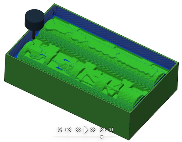
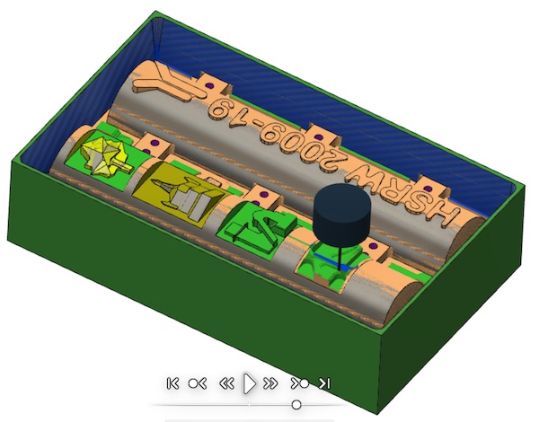
My final strategy was to break up the job into various regions according to the kind of milling that would be required to do them. Here is the order in which I undertook the tasks:
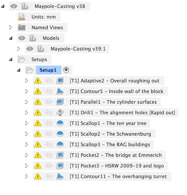
The first Adaptive step was used to clear out the stock and expose the model. I left a full millimetre of additional stock on everything in case the machining runs into trouble when I start cutting for real. I figure this will be the messiest of the steps, so I want to give myself the best chances of succeeding when the mill starts up for real.
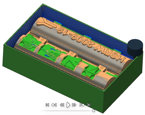
The second step seemed natural - clear off the outer walls of the mould. These are simple flat surfaces with a bit of a slope (8°) to help get the negative casting out of the mould later. There was no need to rough this section, so I started right away with 0.1mm steps.
The Parallel1 step went over the surface of the cylinders from one side to the other. I set a very fine step down and step over of 0.05mm and left no extra material. This was the first finishing cut of the process. The flat cut across the top of the HSRW numbers & logo took a lot of time, but in the end the surface finish looks excellent.
I then drilled out the twelve alignment holes. These are 3mm holes which I’ll stuff with dowels later to line up and seal the two halves of the mould when I go to make the final positive part. The drill step was uneventful.
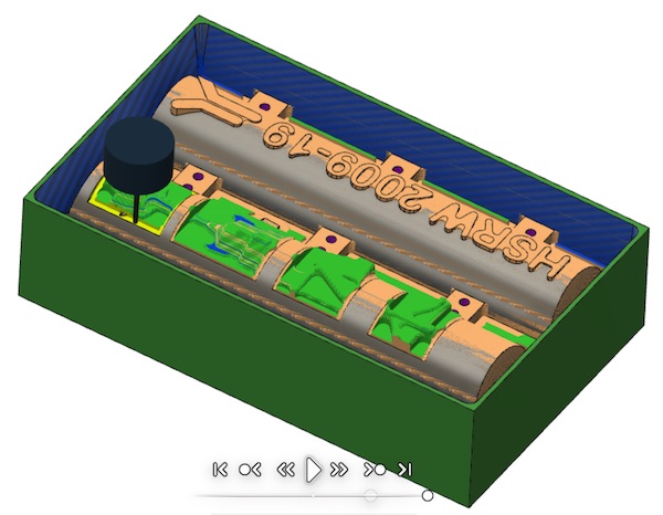
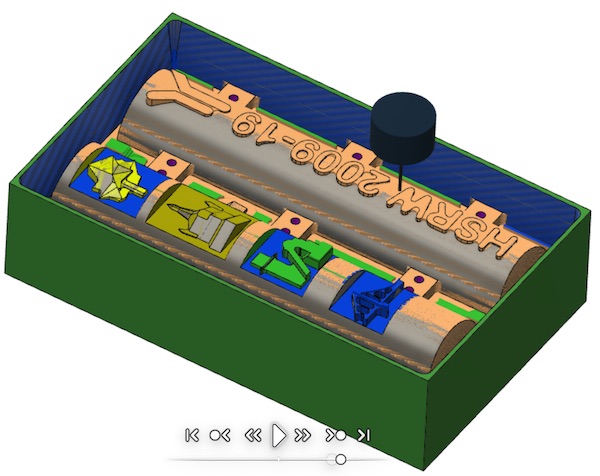
The next four steps cut out the story boards on the left hand cylinder. I had to go back to the model a few times to clean up some extraneous details that had managed to sneak past the model simplification I had done before combining everything. Fusion’s timeline was a godsend for this.
The first two storyboard panels presented no big problems to the Scallop strategy.
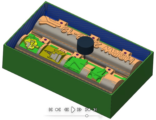
For the third panel, representing the RAG mine buildings in Kamp-Lintfort, I switched to the smaller 1.0mm milling bit, and suddently I had all kinds of problems getting the code to compile. In the end, after several hours’ tweaking, I found a set of parameters which would allow the job to complete without collisions or other crashes.
The fourth panel was a nightmare. Something about the way the model was made left some bugs that I couldn’t smooth out. I went back to the model at least three times to simplify the design. At one point I had three different strategies going on subsections of the panel trying to build something that would work. In the end, I finally chose the Pocket strategy and tweaked the settings until it agreed to finish the job. The final carving is still buggy, in that it produces an earlier, more complex, version of the bridge artwork, but I’m actually ok with that, so I’ve left it with the bug intact.
One the storyboard cylinder was complete, I turned to what I thought was the simpler cylinder. It turned out a little differently. In order to carve the letters, numbers and logo properly, taking into account the curved surface of the cylinder, I eventually had to create a sketch back in the model and use that as the limiting selection border in the Pocket strategy settings. With the very fine detail settings, this strategy step ends up being very long, and I’m not sure actually that it does very much new and different from the Parallel step earlier. I’ve left it though, as it does seem to clear out the insides of the zeros and tidy up a few curves around the other characters.
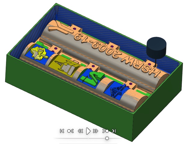
The final step was to separate the model of the overhanging turret from the nearest cylinder, which was straightforward to do with the Contour strategy.
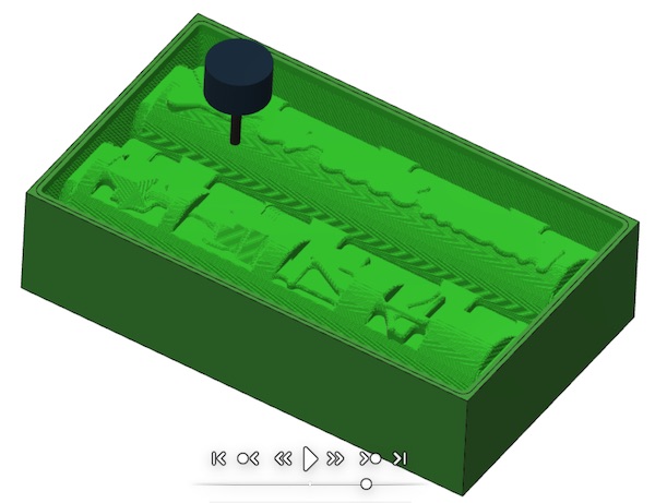
The Final Result
The final result, in simulation at least, looks really good. All of the milling strategies look like they have achieved the required surface finish and there are no collisions with stock or other errors in the process.
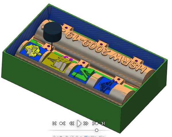
All that’s left to do is to very carefully measure the tools again, and then input the machining speeds to be compatible with the Roland Mill.
NC File
After all of the trials and tribulations with the Fusion 360 simulation, creating the g-code (NC file) was a walk in the park. There is a menu called “post-processing”. One just selects that and chooses the right built-in milling machine (Roland MDX-40A), and the file is created automatically. This gets copied to a USB stick and sneaker-netted over to the laptop that runs the Roland. Loading the code into the Roladnd VPanel program is quick and easy.
Material
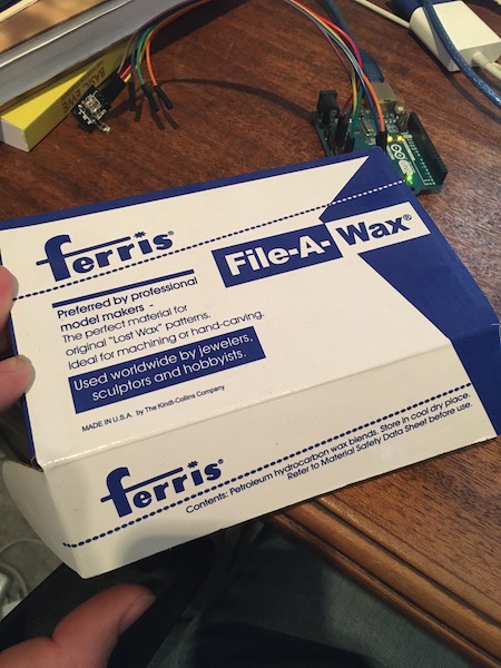
The moulding material we’re supplied with is called Ferris File-A-Wax and is made by Freeman Manufacturing and Supply Company. The block is 3-5/8” by 6” by 1-1/2” in size. The datasheet is available online here. The datasheet describes the blue material as “poor” for high-speed CNC machining, but given that pretty much everyone in the FabWorld has used this material for their moulding and casting, I’m going to assume it’s good enough. It would be interesting, in another life, to try the gold or orange varieties to see how they differ.
Machine Set-Up
The first step in machining the positive mould is to attach the block to the stage of the milling machine. This we did with double-sided carpet tape, having made sure that the block was placed as close to perfectly parallel to the edges of the stage.
Then I used the Roland’s built-in zeroing tool to calibrate the z-axis. The tool is set in the machine firmware such that when the tool contacts its upper surface, the machine is zeroed to the top of the stage, which in this case is the bottom of the wax block (stock).
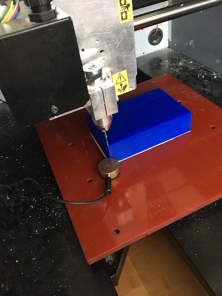
Once the z-axis was calibrated just away from the model origin, the mill was retracted to a safe height and driven to a spot centered in x and y on the corner of the block and in the middle of the milling bit. In retrospect, I should have set it such that the cutting edge was lined up with the outside of the block in x and then in y, but there was enough wax that that didn’t matter.
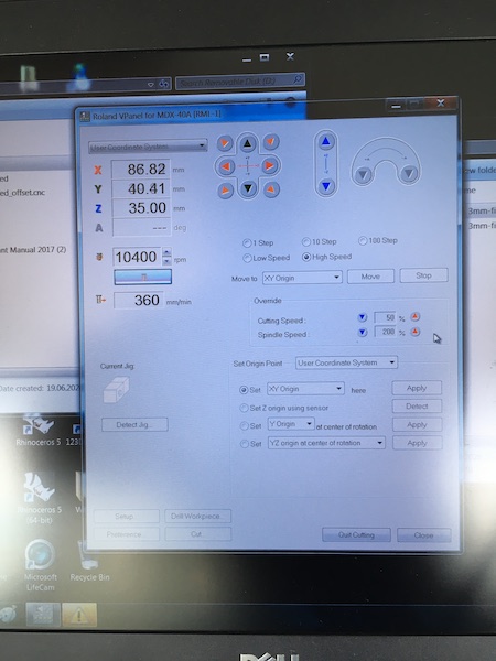
We selected a cutting speed of 10400 rpm and allowed the machine a feedrate of 360 mm/min.
Milling
How nerve-wracking is this going to be?
The machine got off to a good start, first with the rough adaptive clearing, and then progressively more detailed as the jobs progressed. In retrospect, I ran the job far too slowly (ie I could have allowed a much higher feedrate), but as there was nobody else using the mill, I just let it run.
The chips came off nicely, and the roughing stages went well:
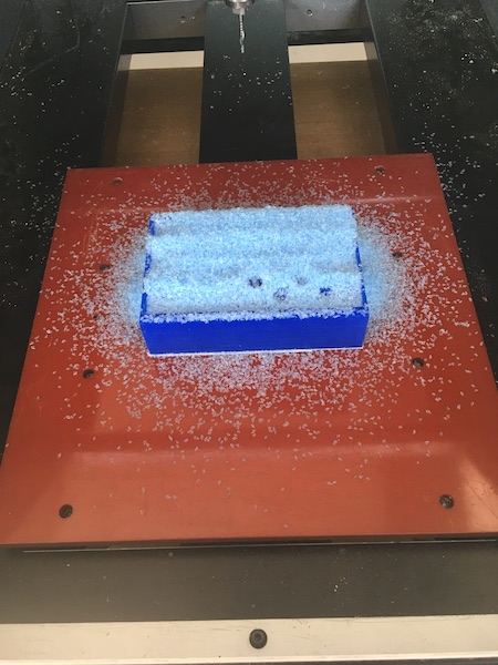
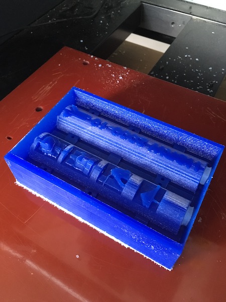
Notice in the last of those three pictures, not all of the holes have been successfully drilled. To fix the problem, I went back to the model and increased the size of the holes by 100um, then created a new drilling job, which was then run after everything else had been completed.
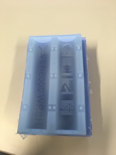
After two long days of slow cutting, the result is gorgeous:
Moulding the Negative
With the milled positive mould complete, it was now time to start on the casting part of the exercise.
Mould Preparation
Once the mould had been cut, I cleaned it up with a knife to remove the long parallel milling marks. I then added some clear plastic side extensions all around the mould to ensure there would be enough base material to give the negative some strength.
The mould was then ready to receive the liquid silicone.
To determine how much volume of silicone would be needed, I filled the mould, with its plastic extensions, with water and weighed the difference between the empty mould and the filled one. The total was approximately 200mL.
Preparing the Silicone
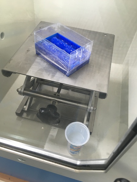
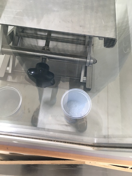
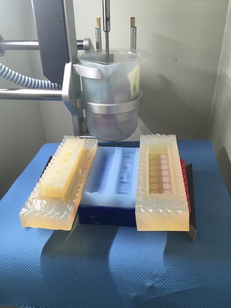
The moulding compound we had available for use is a two-part silicone called EcoFlex 00-35. The mixing ratio is simply 1:1. Using a pair of cleaned out yogurt containers, I poured out equal parts of about 100mL each. The two containers were placed in the vacuum chamber to remove any dissolved gasses. The bubbling is obvious in the right hand container in the picture below.
Once the two parts stopped bubbling, I mixed them carefully together. The goal was to pour slowly and without creating any roll-under on the surface, so as to avoid adding any air to the mix. I then stirred the mix carefully with a wooden tongue-depresser and returned the mix to the vacuum chamber for another round of degassing.
Pouring
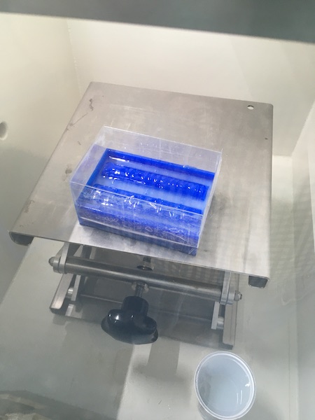
The positive mould includes several holes and plenty of small detail elements. To ensure that these areas were sufficiently covered in silicone and that no air cavities formed between the mould and the rubber, I proceeded in three steps. First I poured only enough silicone into the mould to reach the tops of the locator holes, then used the tongue depressor to fill the holes as best I could by letting a narrow stream of rubber flow into them. Next I returned the mould to the vacuum chamber and offgassed the silicone.
Once the bubbling stopped, I removed the mould from the chamber and added another layer, this time up to the top of the details, and again used the tongue depressor to fill in the small indent shapes over the surface of the mould. When that was done, I degassed the silicone again.
Finally I filled the mould up to about 8mm above the top of the blue wax mould and completed the degassing.
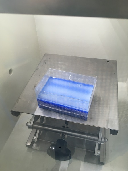
It was mesmerising in some way to watch the bubbling of air out of the silicone. I released the vacuum once as soon as I noticed the silicone beginning to set.
Demoulding
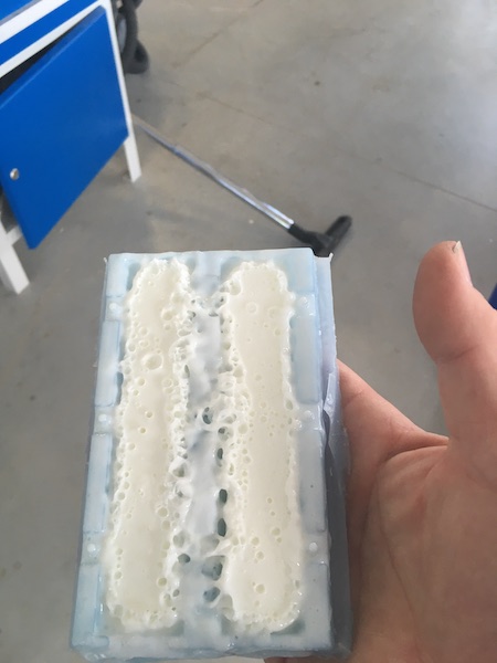
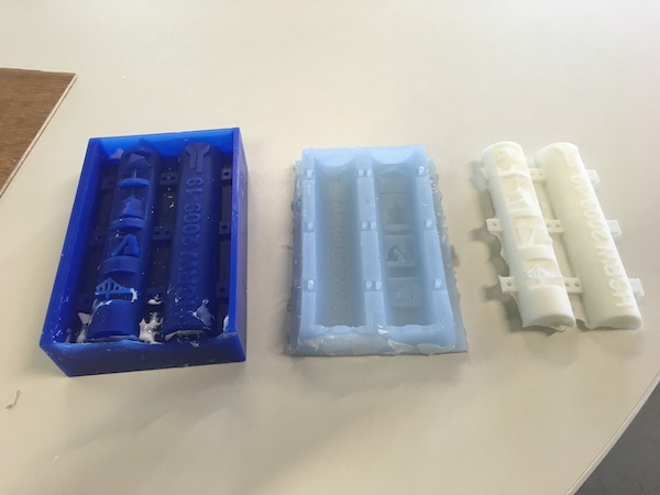
There was a bit of worry that the silicone might set with many bubble inclusions, but as can be seen from the result below, the worry was unfounded.
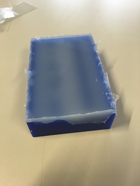
The silicone negative felt fragile as I began tugging on it to remove it from the mould, but with some even peeling and careful prying, it came out completely intact, with a surprising amount of detail. The three-step pouring process worked out well, with even the blind holes and the gaps in the bridge of the lowest panel properly filled.
Casting the Positive
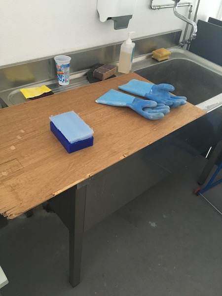
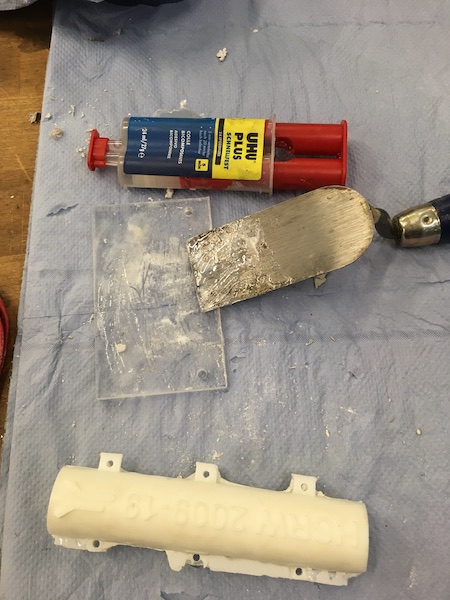
With the silicone mould completed, it was time to start the casting process. The casting material of choice was a polyurethane called NEUKADUR ProtoCast 105. The process of pouring and mixing the chemicals is a messy one, so I grabbed a bit of sacrificial plywood that was lying around and made myself a temporary counter.
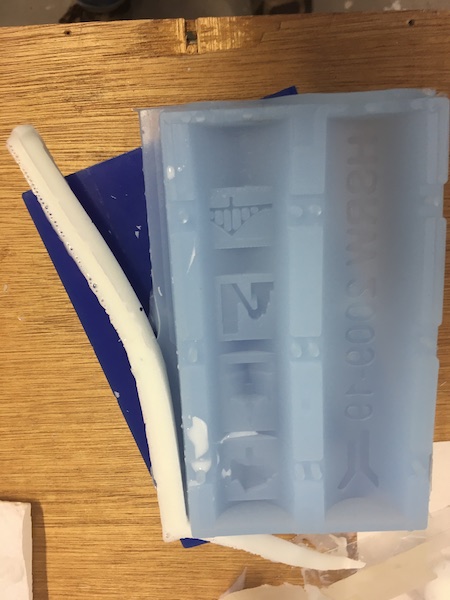
The chemicals were a little old, so I thought best to try a test run first to be sure that they wouldn’t stick to and wreck the silicone mould. The white material around the edges of the mould in the pic below left is the nearly hardened polyurethane. Apparently I hadn’t let it set long enough, because as shown in the right hand picture, it peeled right off the silicone.
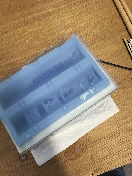
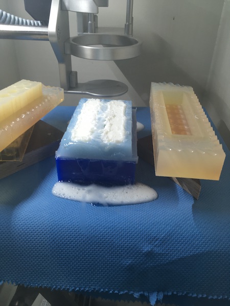
Satisfied that the polyurethane would not damage the mould, I moved my workstation to the vacuum chamber bench and set up inside the chamber. The silicone rubber mould can be seen in the pic below, with two harder bits of mould being used as reinforcements to hold the outer walls straight. The plastic pot in the background has a disposable liner in which I will mix the polyurethane.
The process of preparation involved mixing Parts A and B at a 1:2 ratio. I mixed up 210g of polyurethane, then degassed the mix in the vacuum chamber. While still under vacuum I poured the mix into the mould. The low pressure caused the material to boil quite spectacularly as it set after 6 minutes.
The result did not look good, but it came out of the mould ok.
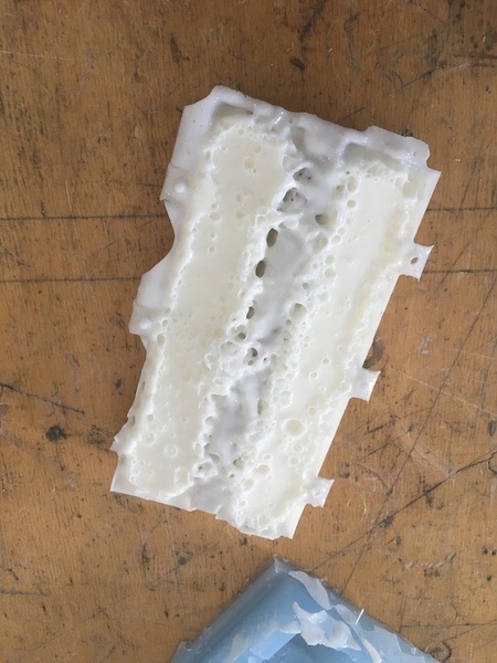
However, the detail on the mould side was fabulous!
The process in three parts:
Assembling the Halves
I sanded the flat sides of both halves. I then glued them together with 5 minute epoxy and held them until the epoxy began to set. I left them overnight, then backfilled the rest of the crack between the two halves with more epoxy. I had to do that twice to completely fill the gap.
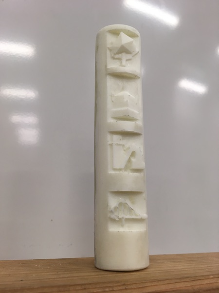
Final Details
After the epoxy had dried for 24 hours, I sanded the joint down to make the final part. All it needs now is a coat of paint.
Datasheets
Moulding: Ecoflex 00-30)
Casting: Protocast 105
Downloads
I’ve made the final model available in two formats:
Group Assignment
Our group assignment for the week can be found here.