20. Project development
Time to start designing the little beast.
I took some time this week to build a little prototype of the dreamboat. Here it is in Fusion360:
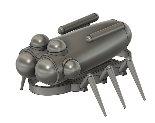
You’ll remember this is the little model I printed for the week 6 assignment. With the virus still wreaking havoc on academia, nothing is happening in the order we might have predicted back in January…
So now it’s final project time, and this week’s assignment is all about getting organised for that.
Project Summary
My final project is about building a six-legged biomimetic walking robot as the starting point for the eventual development of an underwater rover. The inspiration is a cockroach or other six-legged insect. The project consists of mechanical and electronic elements, and is operated by distributed software control.
The design is modular, with each of the six legs designed, manufactured and programmed identically. The only difference between the legs is the ID code they respond to in the communication segment of their microcontroller code.
Mechanical Design
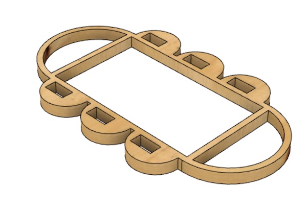
The chassis of the robot is a plywood base with two aluminum skids attached on its underside to provide some additional stiffness & strength, and to serve as the frame on which the electronics board sits.
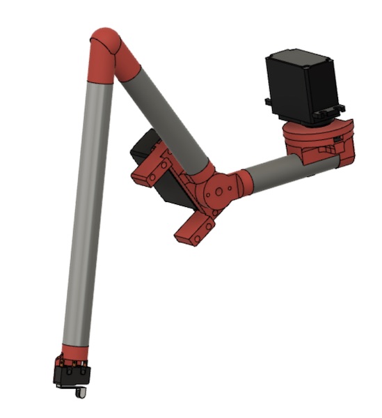
The legs are made of aluminum cylinders connected with 3D-printed joints and actuated by a pair of servo motors. One servo sweeps them forward and aft, whiel the other lifts them off the ground and sets them back down again. A microswitch at the end of the leg provides feedback to the microcontroller about whether the foot is in contact with the ground.
The legs attach to the sides of the chassis and the electronics board fits in the middle. The final state of the CAD is as shown below.
Electronic Design
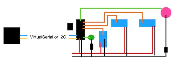
Each of the legs is controlled by an AtTiny84 microcontroller on its own board. The boards are set up with three 3-pin headers to connect to up to three servo motors on each leg. A fourth header is provided for the connection to the microswitch on the tip of the foot. An external crystal (20MHz) is used to ensure perfect timing. A set of four LEDs are provided for debugging purposes and some pleasant visual action on the robot. Two of the microcontroller pins are set up for the communication system with the driving board. The architecture for one leg looks like this:
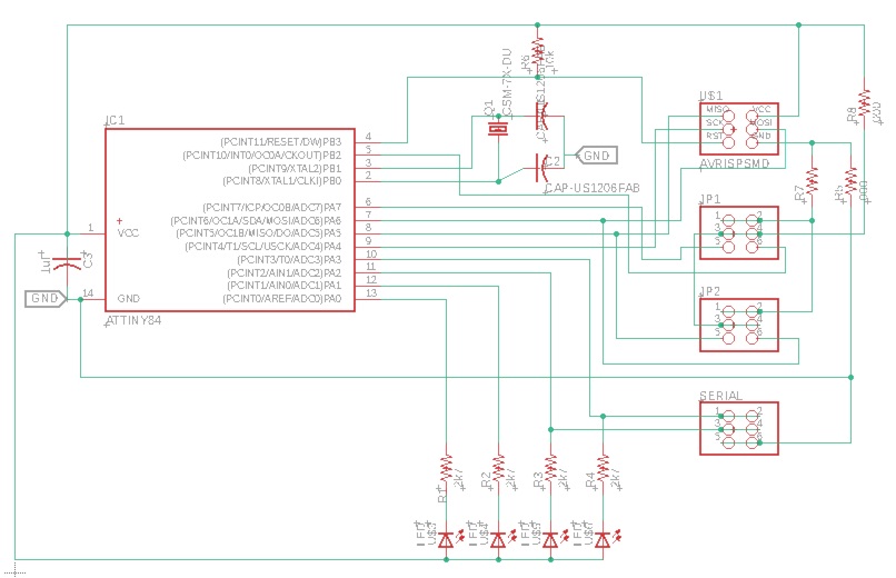
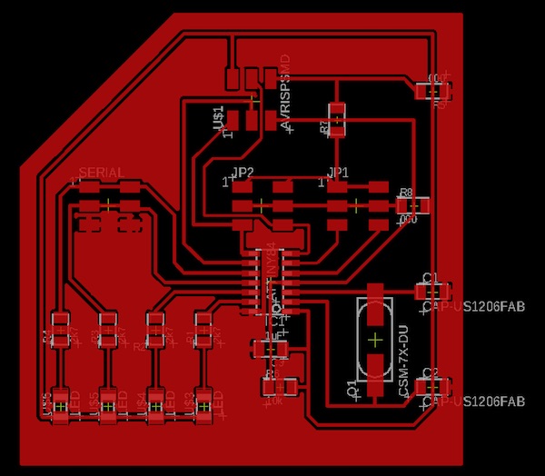
The circuit design of each board is straightforward. Starting from the microcontroller, the various pins are all connected either to LEDs or to pin headers. A capacitor is connected between Vcc and GND to smooth out any noise. Each of the LEDs is obviously connected in series with a resistor to control the current. Finally a resistor between the RST pin and Vcc ensures that the chip doesn’t reset during operation. The circuit diagram looks like this:
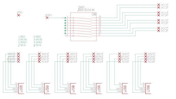
To improve the robustness of the electronics, a footplate with a series of connectors was designed into the machine. The “circuit” is basically just a set of headers connected to some USB-A sockets, and a power bar consisting of a set of microswitches.
Software Design
The robot’s software architecture is straightforward. An Arduino Nano provides the overall control, sending signals across a SoftwareSerial bus to all of the leg boards. Each signal includes an address code as its first two bytes, and only the board with the matching address will respond to the command, complete the task requested, and return a completion message. The central controller waits for the completion message before sending a new message out into the bus.
The leg boards respond to two commands: “sweep” and “lift”, each with a directional modifier (“fwd”,”aft”,”up”,”dn”). In the “sweep” routine the shoulder motor moves the leg through a 100° arc. There is no feedback control on the sweep motion. In the “lift” routine, the elbow motor moves the foot through a 45° arc. If the movement is down, it checks at the end of the motion to see if the microswitch is closed. If not, it lowers the foot in 5° steps until 75° is reached. Either the switch closing or 75° will stop the “lift” routine and send a signal back to the controller.
The original idea was to move in an alternating tripod gait, but design constraints showed that to be too ambitious, so the robot is programmed to move in its own creative gait pattern. In the first step, all shoulders sweep aft simultaneously. Then each of the legs individually lifts up, sweeps forward, and lifts down. Once all six legs have thus stepped forward, the cycle repeats.
A distance sensor on the front of the robot ensures that it stops before it hits anything.
Manufacture
The following digital techniques were used in the physical manufacture of the robot and in the implementation of its electronic and software control system.
| Method | Component |
|---|---|
| Lasercutting | Chassis |
| 3D-Printing | Leg joints |
| CNC Milling | PCBs |
| Stuffing & Soldering | PCBs & Footboard |
| Electronics Design | Leg boards |
| Output Control | Leg servos |
| Sensors | Leg microswitches, body sonar |
| Networking | SoftwareSerial with addressing |
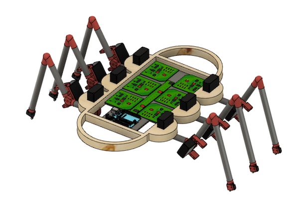
The final beast looks like this:
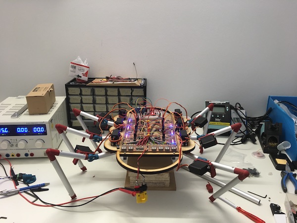
State of the Project
The checklist asks a few pointed questions about the state of the project at the time of writing and the plan to finish up before the deadline. This report is being written one week before the final submission deadline.
Completed Tasks
The mechanical design is as done as it can be. There are still improvements that could be made, but it works. The robot can stand up and do push ups. That is good enough to demonstrate the mechanical feasibility.
The electronic design works. Power is distributed as expected and the moving parts all move on cue. The backbone and footboard ensure that the individual boards do not need to be disturbed for reprogramming, and individual boards can be easily reset as required.
The programming is started. The leg boards all move their leg motors in a predetermined pattern as planned. They are able to detect the state of the microswitch. Network communication is one-way and very limited (a pin simply goes high or low), but it is there, and the legs respond as expected.
Still to do
From the original design, the only “to do” task remaining is the programming. The final gait pattern has just been decided, and now it needs to be implemented in the software.
There are still a few electronics upgrades that are going to be required before the robot is reliably able to walk anywhere. Each of the motors needs a capacitor in series to ensure that current spikes don’t reset the microcontrollers. If that doesn’t work, then the next step will be to provide separate power supplies to the boards and motors.
What has worked
By and large the statics of the mechanical design are ok. The final 3D printed designs are holding. The electronics works. The backbone and footboard improved the reliability immensely. The simple networking worked alright, though its function was very limited.
The machine does push-ups, which is proof that it works.
What hasn’t worked
The power to the motors has been a problem. Either I underspecified them, or they’re just not getting enough power through the circuit boards. It might also be the bench power supply that’s just not up to the job of delivering enough current quickly.
There is a long list of failed prototypes. See the diary chapter of my final project report for the gory details. The 3D printed parts have had to be redesigned and reprinted several times. The wooden frame is flexing and will eventually fail.
The software had to be redesigned several times. The first attempts at using a sophisticated servo control library that would have made it possible to drive three motors had to be abandonned, though I think that decision may have been a bit hasty, so I might come back to this library again later.
The robot cannot stand the way I had envisaged. I wanted to make a machine to walk in an alternating tripod gait, but there just isn’t enough power in three servos to hold the machine stead, and the centre of mass is not where it needs to be, so the legs are unevenly loaded and the robot doesn’t stand up straight on only three legs.
What questions need to be resolved
The unknown about the current draw into the servo motors is the immediate question that needs an answer. The experiment with the capacitor will tell a lot.
The second big question is how to coordinate the one-leg-at-a-time gait. It will mean adjusting the sweep angle to make sure the legs don’t collide. That will required some experimentation.
What will happen when
Here are the steps that need absolutely to be done:
- Capacitors on the motors
- SoftwareSerial protocol needs to be set up
- Reprogram leg motors to separate “sweep” and “lift”
- Work out maximum sweep angles
- Make the microswitch end effectors work
- Sort out the coordination of the one-leg-at-a-time gait and the programming of the controller
- Finish documentation
- Celebrate
- Present (in Jan)
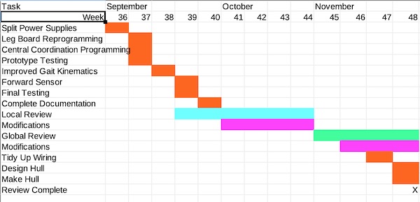
Time plan
With everything else that went on this summer, it was not possible to get back to the robot after the last minute rush that happened before the June deadline. I was only able to get back to working on my final project in early September. I divided up the rest of the project into small pieces to be sure that I could get everything done on time. Here is a Gantt Chart showing the steps that remain to do and an approximate time frame to aim for.
What have I learned
I was never really expecting it all to “just work”. That’s for sure. It didn’t disappoint. The journey here has been as important as the result.
I knew there were some unknowns in my design, and in retrospect, some more time spent analysing the forces required in my design so that I could specify the servo motors properly and design the shoulder parts more robustly, would have helped a lot.
I learned a lot about electronics. The exercises in the FabAcademy prepared me for the design and implementation, but the problems that came up outside the curriculum, as it were, such as the power considerations and that a microcontroller can be powered by the voltage on a serial line, were unexpecteds.
I learned a lot about documentation. This summer has been a nightmare of multitasking, and it simply wouldn’t have been possible to keep this project going if I hadn’t documented as I went along. The lessons learned at each step of the way would have had to be repeatedly relearned.
And finally I learned not to hesitate to ask for help. Dr Google is pretty good at the simple stuff, but when it got challenging, it was the FabLab staff that made the difference. Thanks to you all.