3. Computer Aided design
The objective this week is to set up, use and get familiar with a variety of CAD tools. When I first started FabAcademy just over two years ago, I had pretty much no CAD experience at all. I’ve come a long way since then, and incorporate several of the CAD packages we were introduced to in FabAcademy into my own teaching. I’m by no means a CAD master, but the skills I’ve learned have opened up new worlds for me.
Not all CAD packages are created equal. It is generally possible to do any given task with any CAD package, but the ease with which that task can be accomplished varies from one package to another. In this week’s report, I present five different CAD packages (ok, well, three CAD packages and two graphics programs) and highlight the sorts of things I’ve been able to do with them.
Powerpoint as a Sketch Tool
I use MS Powerpoint as a general scratch pad for first concepts. It’s not generally considered a CAD tool, but for straightforward 2D layouts, as for example in planning the course layout of a human-powered submarine race or the new lab space in the department, the simple vector graphics are often plenty good enough.
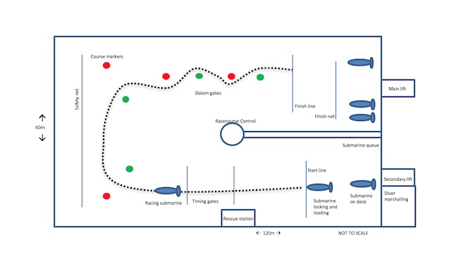
The rectangles can be dimensioned and positioned using the shape format tab. Copying is easy to do, and drag-n-drop is simple. Cloning isn’t possible, but quick reformats using multiple selection (cmd-click) work easily.
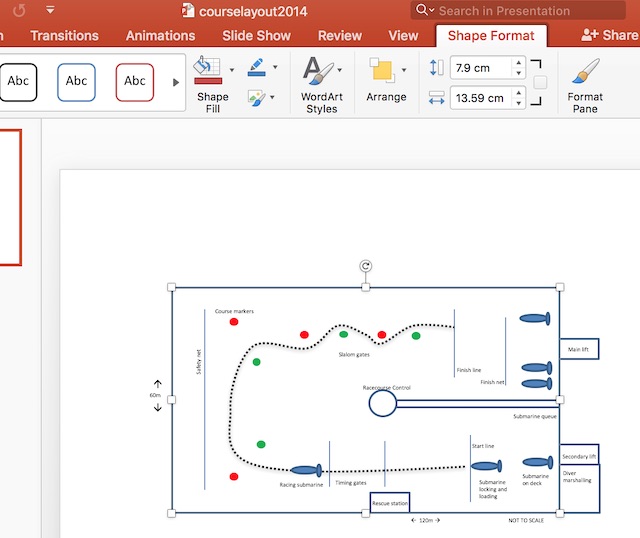
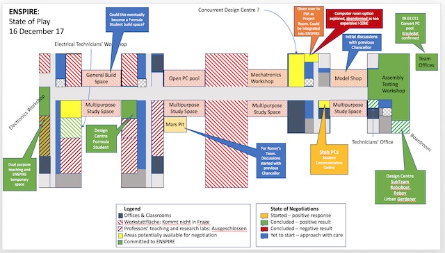
Scale drawings can easily be made. Parametric modelling isn’t possible with the direct commands, but one can (though I haven’t here) use vbscript to program sizes that way (see below). This is an annotated drawing of the faculty’s buildings, showing the state of the development of the ENSPIRE project, which will bring FabLab-like facilities to the Cleves campus of the university.
3D modelling is harder to do in powerpoint, but by playing with the perspective, one can at least illustrate the point, as I’ve done here by drawing some primitive shapes over top of a jpg my students provided me of their submarine design from last year.
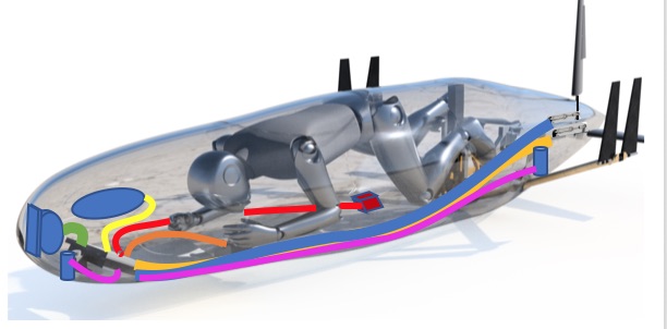
The intent here was to show the locations on the model of the electronic instrumentation I wanted them to add to their design. It was also useful to show where the cabling would have to run. It took a few minutes to draw in powerpoint. It would have taken hours to draw the various components in a traditional CAD package like SolidWorks or Fusion360. Since in this case the wiring was all going to be measured, placed and cut in situ, there was no need to draw the model in any more details.
2D parametric design with PowerPoint
My wife and I are looking to build a house. To choose from the gazillion floor plans out there, we’re starting from the furniture we have, out of which we’ve created our home in every one of the houses we’ve lived in over the years.
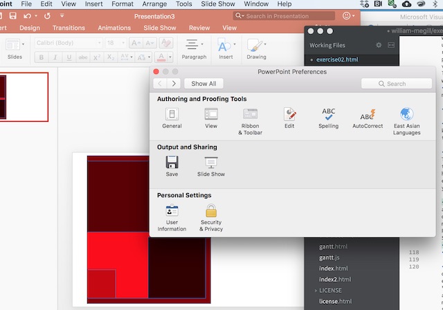
So to model the 2D floor plan very simply and easily, I’ve gone for a parametric version of powerpoint using the VB scripting language which is built into it. The first step is to enable macros, which on a mac is done in PowerPoint:Preferences, Personal Settings, Security&Privacy. Select enable all macros.
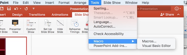
The VB script editor is called using Tools:Macro:Visual Basic Editor:
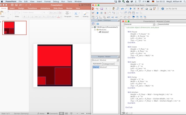
The VBscript program is set up like any other. It starts with setting up the display and defining the required objects. In this case, my house is one half of a duplex, with three rooms and a hallway on the ground floor. I defined five objects, one to represent the outer dimensions of the house, one for the inner livable space, and one each for the living room, kitchen and guest bathroom.
{
Sub moenichsfeld()

'clear slide before running code

    For Each sld In ActivePresentation.Slides
        TotalShapes = sld.Shapes.Count
        For i = TotalShapes To 1 Step -1
            sld.Shapes(i).Delete
        Next
    Next

    Set myPlan = ActivePresentation.Slides(1)

' create objects

Dim NumShapes As Integer

NumShapes = 5

For i = 1 To NumShapes

    With myPlan.Shapes _
        .AddShape(msoShapeRectangle, 90, 90, 90, 50).Fill
            .ForeColor.RGB = RGB(255 / NumShapes * i, 0, 0)
            .BackColor.RGB = RGB(170, 170, 170)
            '.TwoColorGradient msoGradientHorizontal, 1
    End With

Next i

' set object handles

    Set house = myPlan.Shapes(1)
    Set innen = myPlan.Shapes(2)
    Set kitchen = myPlan.Shapes(3)
    Set bath = myPlan.Shapes(4)
    Set living = myPlan.Shapes(5)
}
With the objects defined, now it’s time to get out the measuring tape and set up some global parameters. I’ve used a scaling parameter to fit the objects to the standard PowerPoint slide and labelled it “m”, so that I can think of it as “metres”. The first bits of parametric design are appearing now, with the wall thickness and the one X_floor measurement defining the dimensions of the livable space.
{
    ' define global variables

    Dim X_house As Double
    Dim Y_house As Double
    Dim A_floor As Double
    Dim X_floor As Double
    Dim Y_floor As Double
    Dim iWall As Double 'InsulationThickness
    Dim m As Integer ' PlanScale

'set design parameters

    m = 50              'overall scale parameter to fit to page
    X_zero = 1          'offset from left side of slide
    Y_zero = 0.2       'offset from top of slide

    iWall = 0.37        'insulation thickness
    A_floor = 80       'floor plan area of house
    X_floor = 8.3      'inner width of house

    Y_floor = A_floor / X_floor
    X_house = X_floor + iWall
    Y_house = Y_floor + 2 * iWall
}
Then it’s time to define the room geometries. Each of the sketches is defined by measurements, and its location on the sketch is defined by relevant parameters starting from the top left corner.
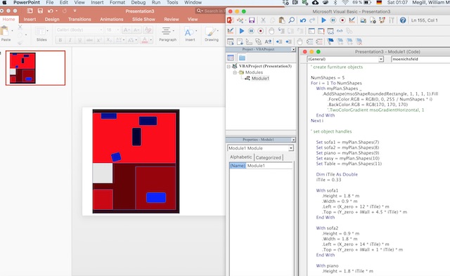
Next we add the stairs. Crudely they’re simply represented by a vertically striped fill pattern. Some more detailed breaking down of the structure, coupled with more judicial use of the fill pattern, would generate a more stairlike graphic.
{
    'stairs

    With myPlan.Shapes _
        .AddShape(msoShapeRectangle, 1, 1, 10, 10).Fill
            .ForeColor.RGB = RGB(200, 200, 200)
            .BackColor.RGB = RGB(0, 0, 0)
     End With
   Set stairs = myPlan.Shapes(6)

    With stairs
        .Height = 2 * m
        .Width = 2 * m
        .Left = (X_zero) * m
        .Top = (Y_zero + iWall + 5) * m
        .Fill.Patterned msoPatternDarkVertical
    End With
}
And finally some of the big bits of furniture.
Downloads
The powerpoint file and its macro are available to download using the first link below. Your security settings might get upset about the macro - check to make sure you’re happy with all of the code in the macro before you change the security settings to allow it to run. The second link is an example of an exported PDF file which could be used for laser engraving, for example.
Powerpoint file with included macro: Link
PDF file for use eg on a laser cutter Link
OpenSCAD
¶My introduction to 3D-CAD has been a slow one. I made it through twenty-five years of engineering (starting in 1993) without ever “learning to CAD”. All of my design work was always done with a pencil, chalk or whiteboard marker. The students then had the task of doing the detailed 3D-CAD work.
The first of the CAD packages I was introduced to was, oddly, OpenSCAD/FreeCAD. The programmatic functionality of OpenSCAD helped a lot to get me into 3D design. The familiarity of the scripting language got me over the hurdle of the steep learning curve of sketches and extrusion which I had seen others master, but which I couldn’t get to stick in my own brain.
The project which got me started was a new device we’re developing in the lab which uses a bionic artificial lateral line to measure air flow through a scuba system. The concept was based on a paper one of my students published in 2016.
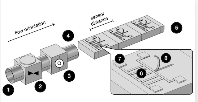
The sensing elements of the lateral line are the curved cantilevers shown extending from the rectangular prism to the right in my student’s drawing (also made in OpenSCAD). The cylindrical object to the left is the air pipe in his experiment, which would become the body of the device I wanted to design.
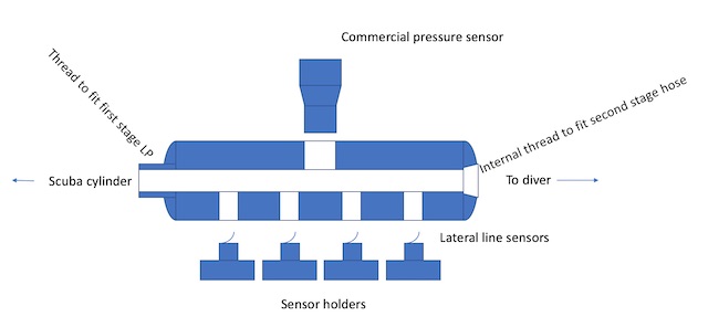
So first to powerpoint to draw a cartoon of the device I had in mind. This took eight minutes start to finish, and it gets across almost the whole concept.
In my pre-FabAcademy life, I would have printed that sketch off, then got out a pencil and done some dimensioning with the other bits of the system (hoses, fittings, sensors), then quietly got started at the lathe and mill, cutting away at a chunk of stainless steel, piece by piece until I had the first prototype in hand.
The new me wants to do things differently, so I got stuck into OpenSCAD. The first step was to dimension the body parametrically. I had decided, completely arbitrarily, to make the device out of a 1” bit of stainless bar (mostly because I had one in the metal offcuts box, and because it “felt right” looking at a scuba tank). The body design ended up looking like this:
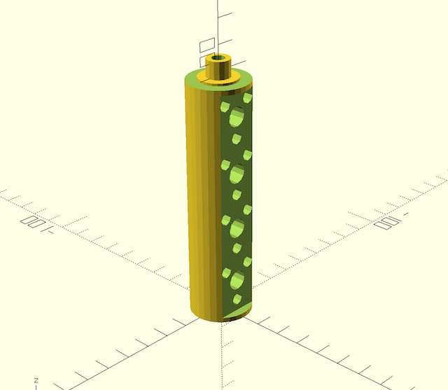
The OpenSCAD code required to draw this shape is as follows:
{
body(15.5,38.5,61.5,84.5,0,98,7);

module body (soc_z1,soc_z2,soc_z3,soc_z4,circle_res,bdylen,stemlen) {

//bdylen=90;
bdyrad=12.5;

    difference () {

        // body
            // outer shell
            difference () {
                union () {
                    // main body
                       cylinder(h=bdylen,r=12.5,$fn=circle_res);
                    // threaded male fitting
                        translate([0,0,bdylen])
                        cylinder(h=7,r=9.525/2,$fn=circle_res); // 3/8 UNF
                }
                union() {
                    // downstream threaded socket
                    translate ([0,0,-.1])
                        cylinder(h=6,d=8.5,$fn=circle_res);  // 3/8 UNF
                    //  metric_thread(9.5,1,5);
                    // upstream hole through threaded part and top of body
                    translate ([0,0,bdylen-15.9])
                        cylinder(h=16,d=8.5,$fn=circle_res);
                    translate ([0,0,bdylen])
                        cylinder(h=7.1,d=5.5,$fn=circle_res);
                    // inner core
                        cylinder(h=bdylen,d=8.5,$fn=circle_res);
                }
            }


        union () {

            // flat surface
            translate ([-12.5,9,2])
                cube ([25,4,bdylen-5]);

            //upper flange
            translate ([0,0,bdylen-1])
                difference () {
                    cylinder(h=1.5,d=26);
                    cylinder(h=1.5,d=16);
                }

            // gauge socket

            for (i=[soc_z1,soc_z2,soc_z3,soc_z4]) {

                translate([0,0,i]) {
                    // sensor hole
                    translate ([0,bdyrad,0]) {
                        rotate([-90,0,180]) {
                            cylinder(h=bdyrad-2.7,r=4,$fn=circle_res);
                        }
                    }
                    // o-ring groove
                    translate ([0,9.5,0]) {
                        rotate([-90,0,0]) {
                            cylinder(h=1,r=4.5,$fn=circle_res);
                        }
                    }
                    translate ([0,5,-8.5]) {
                        rotate([-90,0,0]) {
                            // metric_thread(4,1,6);
                            cylinder(h=6,r=2.5,$fn=circle_res);
                        }
                    }
                    translate ([6,5,6]) {
                        rotate([-90,0,0]) {
                            // metric_thread(4,1,6);
                            cylinder(h=6,r=2.5,$fn=circle_res);
                        }
                    }
                    translate ([-6,5,6]) {
                        rotate([-90,0,0]) {
                            // metric_thread(4,1,6);
                            cylinder(h=6,r=2.5,$fn=circle_res);
                        }
                    }
                }

            }

            // pressure sensor socket
            translate([0,-bdyrad,bdylen/2])
                rotate([-90,0,0]) {
                    cube([25,16,5], center=true);
                    cylinder(h=12.5,r=5.9,$fn=circle_res);   // 11.8mm for 1/4BSP thread
                }
        }
    }


}
}
Initially I generated the model using numerical dimensions, so that I could see the elements fitting together, and so that I could properly translate and rotate everything to fit. Later I swapped most of the numerical dimensions for parameters, which made it straightforward to redimension when I realised I’d underestimated the size of some components.
OpenSCAD works with union and difference commands to make shapes. In this case the shapes were all pretty simple: except for two flat surfaces made with cubes, they’re all cylinders! The trick was then just to get them translated and rotated to the right place and orientation. The hardest part was getting the order of the union and differences right.
The parametrisation using the arguments in the module line made it easy to adjust the location of the various elements of this design so that they would line up perfectly with the other components as they were added. It also meant that once the design was completed, I could quickly change the separation distance between the sensor holders - a feature that turned out to be very useful as I began to manufacture the device and realised I’d made a few design errors.
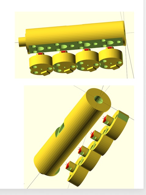
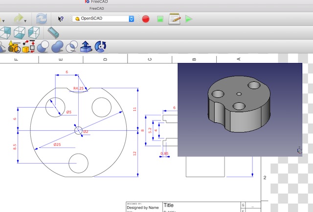
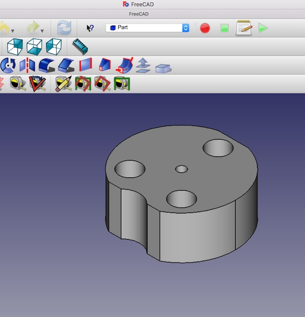
The rest of the design of the device involved making four sensor holders, the four sensors, and three bolts per holder. The finished design looks like this:
Once the design had gone through a couple of iterations to make it possible to actually manufacture (as one point, I had designed holes to be drilled at an angle to a round surface - no way that was going to go well), it was time to transfer the design to FreeCAD to create the drawings so that I could machine it.
FreeCAD
FreeCAD. Wow. I’ve taken no time at all to develop a healthy love-hate relationship with this program. I think if I’d come directly into it, I might have had a different perspective, but I came into it really only as a tool to make 2D manufacturing drawings for the parts I’d designed in FreeCAD. So it was into the deep end directly with importing the code.
FreeCAD and OpenSCAD are actually really well integrated. Once the parametric design was complete in OpenSCAD, all I had to do was to File:Import, and voila.
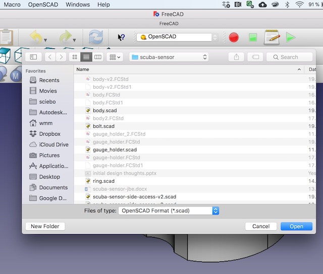
Once the data was imported, then FreeCAD works pretty much as expected. There is one apparent bug in the display of the windows. At first opening, the 3D window opens on top of the drawing, and there’s no way to move it. The quick fix is Window:Cascade. Then the two windows can be moved apart.
The parts come into FreeCAD ok. I didn’t do any modification of them in this package, since I wanted to retain the purely parametric design from OpenSCAD.
Then the next step was to prepare the engineering drawings. FreeCAD made that easy. The drawing is made by using the fourth button from the left on the third toolbar. From there, the drawing comes to life quickly, and then dimensioning is straightforward to do with tools supplied.
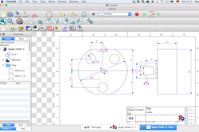
Armed with the drawings, I went to the lathe and mill, and started cutting stainless. I ended up breaking a few bits trying to drill small holes, and pushed one or two holes too far through the material, which meant I had to backfill them with an epoxy paste. But I got there in the end.
The last step of getting the whole thing manufactured was to modify the commercial pressure gauge, shortening its threads to fit into the wall thickness I had available.
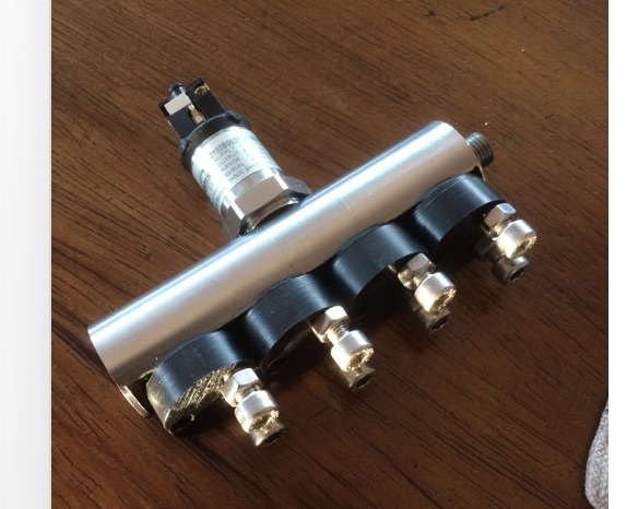
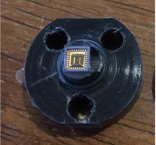
At some point, as I was assembling the final device, I realised I’d made a schoolboy error. The goal with the sensor carriers was to place a set of semiconductor gauges into the flow. The problem that appeared as I started to assemble the device was that the stainless steel carriers would of course be completely conductive and short out all of the electronics! Sigh. So back to the lathe and mill. I made the chip carriers this time out of a bar of nylatron I had kicking around.
The sensors were unfortunately all dud on arrival, so it wasn’t possible to get the device built.
Epilogue
Part 1. The design I reported above was made two years ago. In the meantime, a new set of sensors has been developed by my (now) postdoc and is nearly ready for commercial release. As soon as that happens (hopefully in March or April 2020), I’ll redesign the sensor carriers, then put the machine together with some appropriate amplifier electronics. If the release happens in time, I’ll try to build the full machine as part of this FabAcademy.
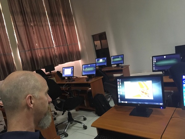
Part 2. Last autumn, I took FreeCAD and Fusion360 to remote Africa, and taught a ten-day intensive Engineering Design class at the Ho Technical University, in eastern Ghana.

The staff there really wanted their students to have access to the latest technology, which they saw as Fusion360. However, the internet connection just wasn’t reliable enough to do the online part of Fusion360, so I installed FreeCAD for them instead, and briefly introduced them to it. The next time I go (next September is the plan), I won’t even bother with Fusion360. I’ll just spend the time teaching them to use FreeCAD. Free, standalone, fast, simple and reliable. That’s what they need. The bells and whistles of the fancier, internet enabled software can wait.
This pic was taken in their computer lab, as I was struggling to install Fusion360.
SolidWorks
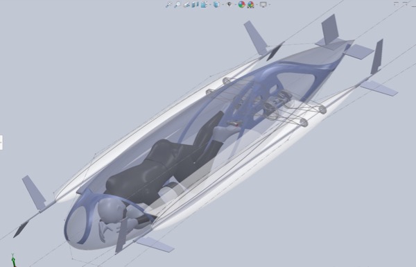
After that initial introduction to parametric CAD, I figured it was finally time to learn 3D CAD for real. Our university has a general SolidWorks license, so that was the natural tool of choice. The need to learn it suddenly got a lot more urgent when it became apparent that the students of the submarine team weren’t going to be able to deliver a hull design on time, so I ended up having to step in.
I won’t go into detail at this stage of the whole learning process involved in getting to know SolidWorks. The key that opened it up for me was finally understanding what was meant by a sketch and an extrusion!
At the end of three intensive weeks learning SolidWorks, I had drawn this puppy:
I’ll come back to SolidWorks again in a few weeks’ time with parametric design in the “Make Something Big” assignment.
Fusion360
I fought with Fusion360 for a long time and resisted learning the new terminology. It just seemed to incredibly complicated and unnecessary, since I had got deeply into SolidWorks and knew how to make things happen in that system. The clincher was the trip to Ho, in Ghana. The university there wanted me to introduce their students to a modern 3D-CAD system, but it was never going to be possible for them to afford a SolidWorks license. The “free for academic use” policy at Fusion360 was therefore irresistable. So over the summer of 2019, I taught myself Fusion360 using their video tutorials. This is what it looked like:
In all seriousness, once I got past AutoDesk’s insistence that their product is somehow “different” from other CAD packages, and realised that the basics of design are just “Sketch and Extrude”, I was away.
And I’ve never looked back.
I have to admit that I really like Fusion360. Some of the graphics are a bit hokey, and there are some annoyances in the way that it does joints (there is a lot more freedom to brute force a “mate” in SolidWorks - Fusion360 requires more finesse and a better idea of the whole design before you start drawing. Not a bad thing, actually.)
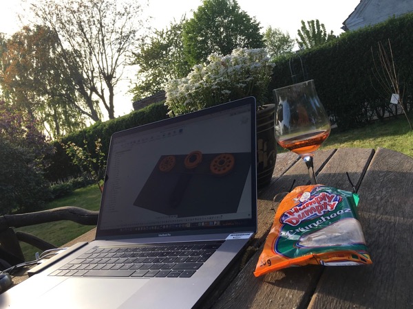
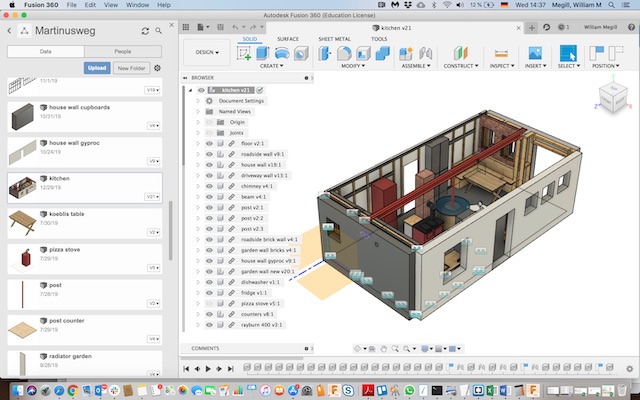
Remember that house my wife and I said we wanted to build? Well that didn’t happen in the end. Instead, we bought an old house and started renovating its kitchen. The original kitchen was a tiny little room buried among five other little spaces in what had been the pigsty on the side of the house back in the 1930s (rebuilt and converted after the war). I could see in my mind what I wanted to do with the space, but to do the planning and to show my long-suffering wife the end goal, I turned to Fusion360. Here’s what came out of the process:
This year I’m going to try the parametric design with Fusion360. I’ll report on that next week in the lasercutter exercise.
Downloads
Scuba Sensor Files