6. 3D Scanning and printing
I was introduced to rapid prototyping, or 3D printing, as it’s now called, when I joined the University of Bath as a lecturer in 2003. My colleague, Adrian Bowyer, and his students were just getting started with their RepRap project, and it was good fun to watch the project develop. We had a super expensive sintering machine in the manufacturing lab, which nobody could really afford to use, and then suddenly we had one in our lab. It was a difficult machine to operate, but Adrian and eD (he preferred it spelled that way round back then) had got the hang of it and started making machines that could make copies of themselves. The project was a significant part of the popularisation of this technology which has made these machines as ubiquitous as they are.
Advantages and Limitations
3D printing, like all manufacturing technologies, has its fors and its againsts. On the plus side, as the basis of additive manufacturing, it has revolutionised manufactuing in many sectors. It is now possible to optimise structures and manufacture shapes that simply wouldn’t have been possible, let alone cost-effective, with traditional subtractive manufacturing. I remember seeing biomiemtic optimisation strategies applied to a diesel engine, which left only the really important bits and solved both the weight and cooling problems, but which looked a bit like a cobweb which nobody could even imagine manufacturing. It turned people off the optimisation techniques, but they’re not turned off any more. Now we have lightweight, structurally optimised airplane seats which are a full kilo lighter than traditional ones. With 400 seats on the plane, that represents a significant increase in available transportable weight.
There are also downsides to 3D printing. The usual printing method, going layer by layer in z, results in shear planes which render the printed part nearly useless for transmitting torques. This is changing, but it’s still a consideration for real mechanical parts. The time to produce a part is not always efficient either. 3D printing a blocky part over ten hours makes no sense when one can do the job with a mill in a few minutes. And my current bugbear is that there isn’t really an efficient way to build the slicing process into the original CAD design so that the new engineers of the future can start making proper use of this exciting new technology.
3D printing
This semester, with the pandemic causing all kinds of rearrangements, the order in which we did the assignments was a bit random. It came down to when we had time, in among all of the other things going on. As a result, this assignment actually happened after assignment 18. Which was useful in a way, since I got to make a simple part first, and then focussed on making a more complicated part as a second operation.
Simple parts
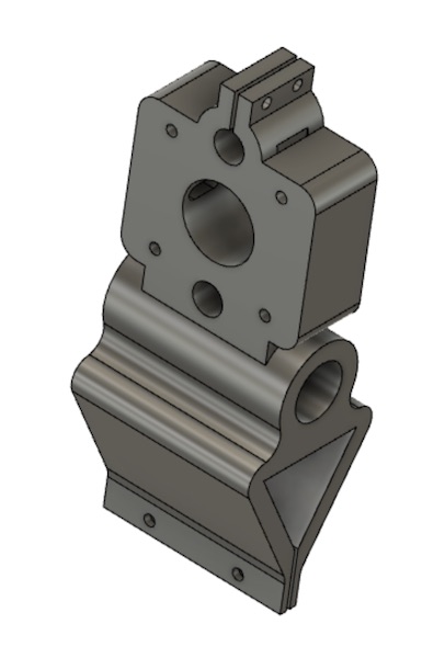
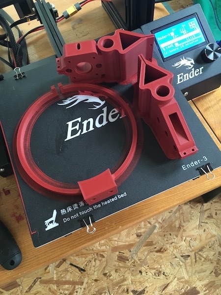
My first go at independently 3D printing some parts was in the context of the CNC embroidering machine that we conceived as a group for our machine building project in week 18. The other members of the team had designed some travellers for the x-axis of our machine, which were to incorporate bushings for travel along the parallel x-axes, the screw fitting that would propel the travellers in the x-direction, and the bushings to hold the parallel y-axes. One of the two x-travellers would also hold the y-motor. The team designed the parts, and I simplified them in Fusion 360 so that they could be scaled and adjusted as required during the machine assembly phase. Here they are after I’d completed the adjustments:
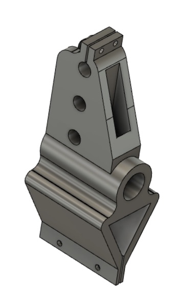
Note in the design, I’ve tried to take into account the diameter of the bead of plastic, which I’m considering to be essentially the equivalent of “kerf” in the lasercutter. I’ve taken a diameter of 0.4mm for the bead, which means that the dimension of any hole has to be lengthened by half that much at either end. All of my bushings are therefore oversized by 0.4mm, and the bolt holes are 3.4mm in diameter to fit an M3 bolt. Similarly the triangular opening in the lower half of the part had to be stretched by 0.2mm in all directions.
The parts have been designed to take the various forces and avoid binding in the mechanism. I’ve tried to ensure that there is balance everywhere, and I’ve used triangles to spread loads out so that the bushings don’t bind. Finally, I’ve redesigned the parts from their original shapes to make it efficient to print them on a 3D printer. This involved shifting the top triangle of the x-traveller from an isoceles one centered on the y-axis rails, to a right triangle flush with the one side. Similarly I adjusted the length of the part overall so that the whole side would lie on the bed, and removed most of the overhangs and regions that would require unnecessary amounts of support material.
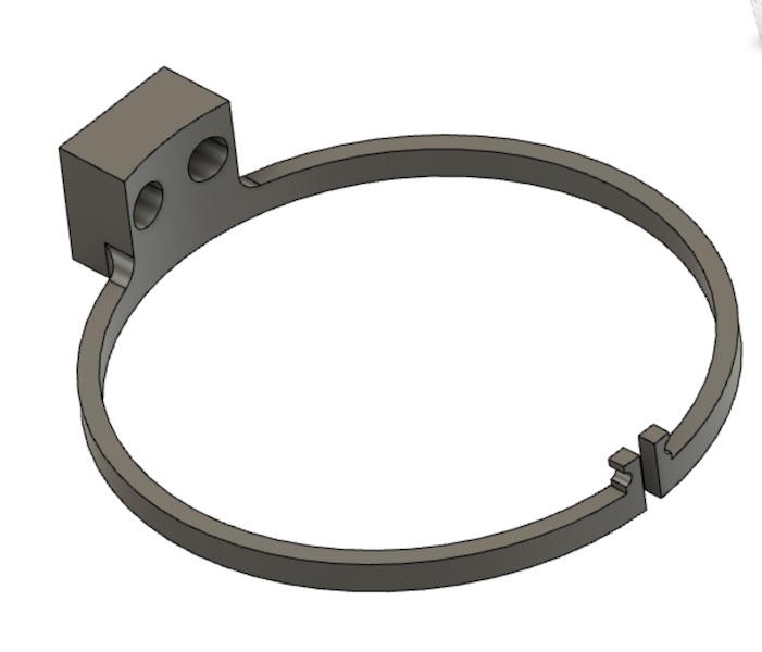
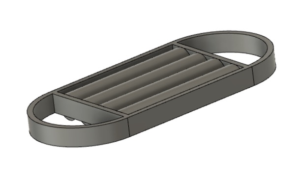
The third part in the collection was the frame we designed to hold the embroidery as we was moved around by the CNC axes. The same considerations had to be taken into account here with regards to the dimensioning and bead width. Also shown are some of the chamfers included to distribute the forces a little more gently from the large lever arms of the ring to the clamp on the left hand end.
More complex parts
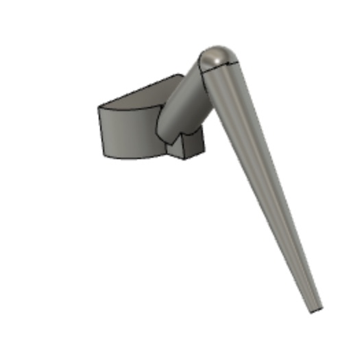
My final project is based on a grant proposal I submitted back in the autumn. The project was about designing and building a 5m long, 17 tonne, walking robot based on a crab, complete with gills for harvesting oxygen directly from the water. My part of the project would have been the six-legged walking mechanism. Unfortunately the funding didn’t come through the first time, but that doesn’t stop the dream!
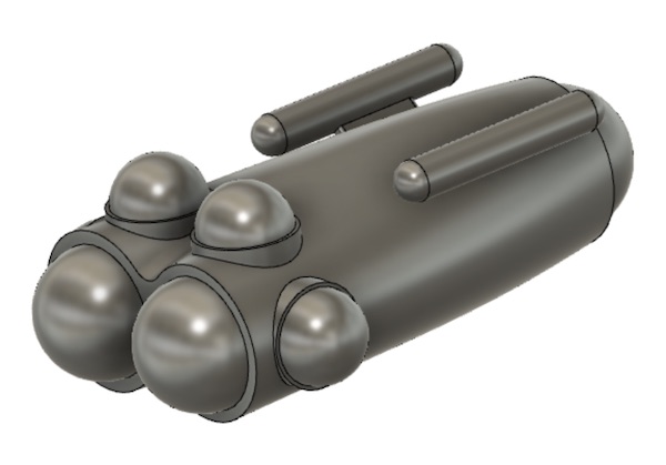
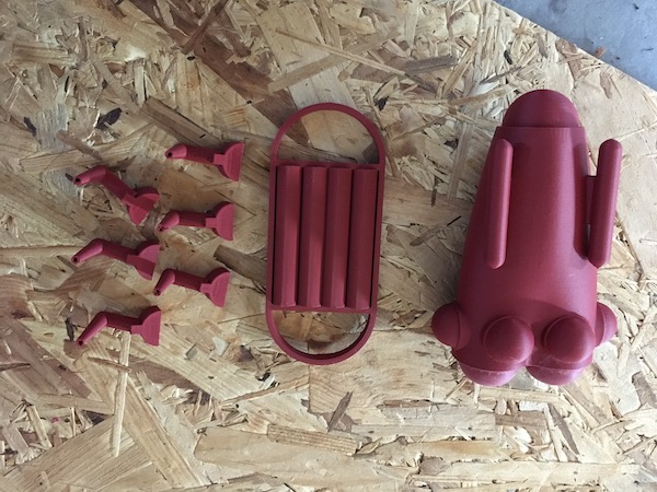
So here in miniature is the dream boat. First the CAD model of the whole machine:
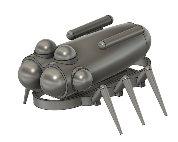
I broke the model up into three components for printing. The hull, chassis, and six legs. The assignment was to print something that couldn’t easily be made with subtractive machining. I could have taken the buoyancy tanks off and made them separately but the lofted form of the hull would have been hard to make. I’d have needed a 4-axis CNC, or I’d have had to very carefully line up the model after rolling it over. Likewise I guess I could have split the legs in two and milled them from above and below. However, by printing the model in three parts, I had everything available overnight, ready for quick assembly. I’d have been weeks making all of the fiddly little parts on a CNC.
Slicing
The CAM process for a 3D printer goes via a step called “slicing”. In this process, the object is cut up like a topographical map and the tool path for the plastic extruder is calculated. Because the plastic is very thin, it is necessary to give it some support as it’s built up layer by layer. Depending on the machine, it is possible to lay some limited overhangs, but the design has to be carefully considered.
Ultimaker Cura
The tool of convenience for slicing in our lab is Ultimaker’s Cura. The current version is 4.6.1. This product is straightforward to use, and can handle any STL file generated by any of the various CAD packages we have. The user interface is nicely intuitive.
Two settings I wished I had known about to start are in the preferences. 1. Turn off “slice automatically” (that will help immensely with repeated crashes) and 2. turn on “Center camera when item is selected”. Two not obvious bits of UI knowledge for Cura on the Mac are that shift-drag translates the image, and ctrl-drag rotates it. Zoom in and out is accomplished using the two-finger drag. The controls for manipulating the model in the working space are all on the left hand side of the screen. There is also a set of predefined camera angles in the bottom left corner.
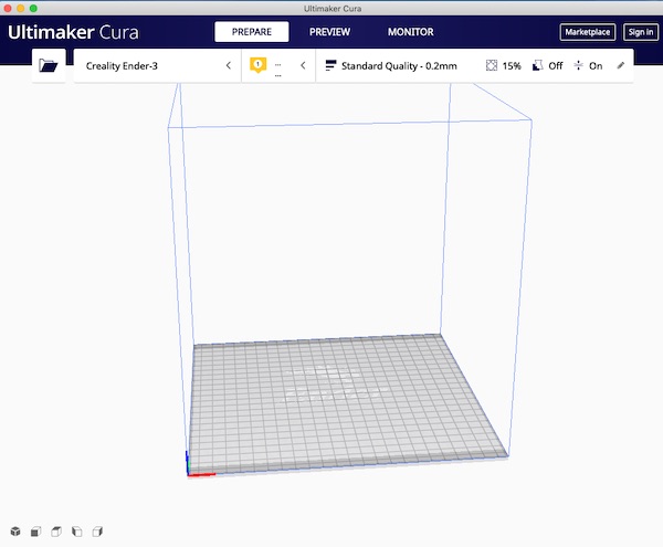
The first step is to select the type of printer, which in my case at the “FabLabchen” in Qualburg is the Creality Ender-3. The next step is to load a model from an STL file. More than one model can be loaded at once, but it doesn’t really help to cut down on print time, and just makes the whole rendering process more liable to crashing the computer.
The next step is to place the model in the 3D space to minimise the amount of support material that will be required. Sometimes this is a little counter intuitive, such as with the hull of my six-legged walker shown below. There was a lot less support material required to print it like a rocket ship than to lie it down.
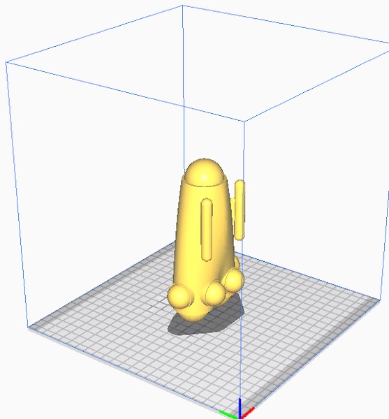
I’d have worried two years ago about printing anything tall, because the printers tended to fail as one got away from the bed, but the materials and printing nozzles have improved amazingly in the intervening time.
Once the model(s) are in place, the next step is to set up the print job. A click on the pencil icon brings up a menu to choose from. The items in the menu can be customised using the gear icon that appears on hovering over any of the items. The default settings seem to work quite well, but there are some places where I made some changes to deal with the geometry of my particular model. In the table below, I have summarised my settings.
| Setting | Value |
|---|---|
| Quality | both set to 0.2mm, half the bead diameter |
| Shell | Default 0.8mm is ok for these models, but for the sewing machine parts where there were stresses in the walls, near the nuts for example, we increased this to 2mm |
| Infill: Density | The default is 15%, which is a good compromise between strength and plastic consumption. I’ve dropped it to 10% with no big troubles. Again, for higher strength parts, increasing to 50 or 60% can be appropriate. |
| Infill: Pattern | There are a series of choices here, which should be chosen depending on how the forces are to be transmitted through the material. I’ve been using “grid”, which seems to work ok for self-support. |
| Material | The PLA I’m using calls for 200°C printing temperature and a bed temperature of 50°C. 100% flow works ok. |
| Speed | The speeds were a big deal and hard to set two years ago when I tried to print, but the technology seems to have settled down now. The defaults of 100mm/s print, 250mm/s travel and 20mm/s initial layer speeds seem to be good. The slow initial layer is important to ensure good adhesion to the bed. |
| Travel | Enable retraction. Otherwise the head will eventually hit the model. |
| Cooling | Enable. Helps ensure the plastic hardens quickly after it’s laid down. |
| Support | This is the artsy part of 3D printing. These settings change each time. I didn’t need any for the embrodiery machine parts, as they were completely self-supporting, and for the rover model, I’ve tried the experimental “tree” support described later. |
| Build plate adhesion | I use “brim”. On the Ender-3 with its bed cover, a brim of 2mm seems to be fine. On the glass plates of the Ultimakers, I found I needed an 8mm brim to ensure enough sideways shear resistance, and even then it didn’t always hold. |
| Experimental | I’m trying the “tree support” mode using the default parameters 40-1-2-5-0.2. The simulator says it’s going to shave an hour and a half off the print job time, so I’m game. It seems to work ok. |
Once the print job parameters are set, then hit “Slice” and save the file to the SD card for transfer to the printer.
Fusion 360
After printing several parts using Cura and going through the nightmare of multiple crashes, it occurred to me to check whether Fusion 360 has a slicer built in. Sure enough it does!
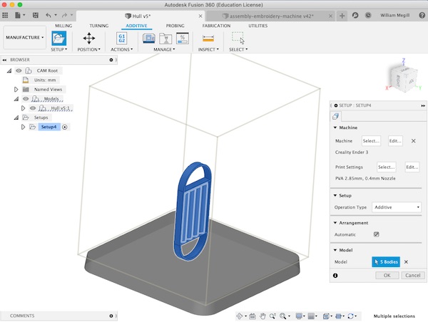
The first step is to select the machine. The Creality Ender-3 was available in the library, so that was easy. The PLA feed stock characteristics 2.85mm and 0.4mm nozzle were there in the default. I set the operation type to “additive” and selected all of the parts of the model that I wanted to print. Better to click on them rather than to go through the design tree, as I couldn’t figure out how to get rid of the hidden parts. Nice to discover that the 3D mouse works, and I don’t have to remember shift/ctrl drag…
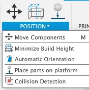
The Fusion 360 UI is nicely laid out. Next step is orient the parts, as with Cura. This is done quickly and easily with the usual Fusion orbit tool. The model doesn’t automatically translate to the floor of the workspace. That has to be done after the rotation using the “Place parts on platform” menu option (or by clicking the falling golf ball on the tool bar).
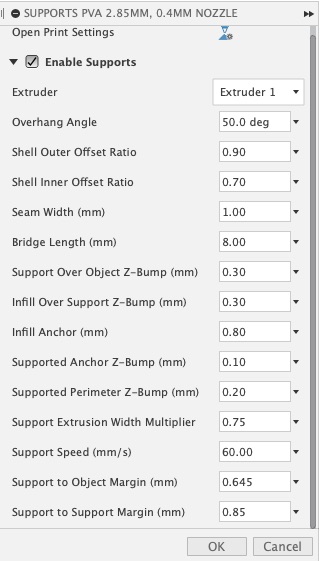
The print settings are next. The defaults are a little different in the Fusion 360 library. I’m not really keen on more experimentation at the moment, so I’ve just set them to the same as I’ve found with Cura to work. The rest I’ve left at the default values. So as not to clutter up this page, the Fusion360 settings are available separately here. One thing that turned out to be important was to enable the printing of a raft. Fusion didn’t have that ticked by default.
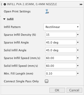
The infill settings I left as they were:
I also left the support settings at default:
One clicks Actions:Generate to launch the CAM processor. It is then possible to view a simulation. The export code for the printer is generated in Post-processing. I selected “generic FFF printer” for that. The g-code is available below:
Downloads
F3D
STL
Gcode
The Printer
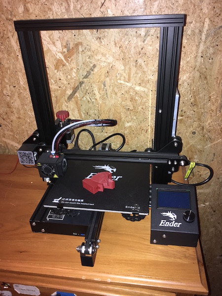
We have a variety of 3D printers in the FabLab, but as we were shut out this semester, I decided to buy one of my own for what is slowly becoming a little satellite FabLab here in Qualburg. The machine my son and I decided on is an Ender 3 by Creality. It seems to have the right mix of features for the price we could afford, and as my research officer has one at home as well, I knew I’d be able to rely on his expert advice if it ever runs into trouble.
Setup
The first step in using the Ender 3 is to calibrate the bed relative to the nozzle of the print head. The recommended technique is to disable the steppers then move the nozzle to within a sheet of paper’s thickness of the bed in one corner, as shown below:
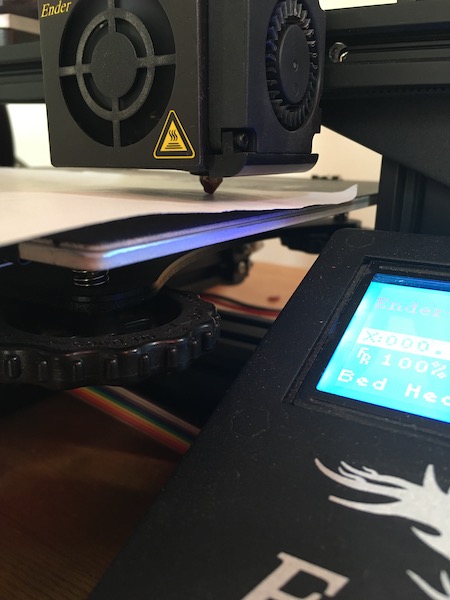
There are four tuning wheels under the corners (one is obvious in the picture above). The technique is to slide the paper under the nozzle and move it back and forth while tightening the tuning wheel. The bed is brought up to the nozzle until the paper can be felt scratching the bottom of the nozzle. When the hairs on your back stand up due to the awful scratching noise, you know you’ve got it about right. Then the trick (as I learned later the hard way) is to back off until the scratching just stops. The bed or printing head is then moved carefully to the next corner, ensuring there are no collisions with the bed, and the process is repeated. It usually takes two trips around the bed to complete the process properly.
Once the calibration is complete, then the g-code can be loaded from the SD-card and the process can be started. The first thing the printer does is run a bead along the left hand side of the bed to clear the nozzle. This also serves as an opportunity to confirm that the calibration is correct. As the printer starts up, it’s worth watching it for a few minutes to be sure that the brim is properly printed and that the first few layers start off correctly.
There are controls on the machine which allow the temperature of the nozzle and bed to be adjusted. The manufacturer of the PLA provides recommended temperatures for the nozzle and bed, so we went with those and they work fine. The nozzle is heated to 200°C and the bed to 50°C. With other printers in previous years, I had to play around with the bed temperature to get the material to stick, but this year, with the default bed cover on the Ender-3, I’ve not had to do anything special. Everything has “just stuck”.
Results
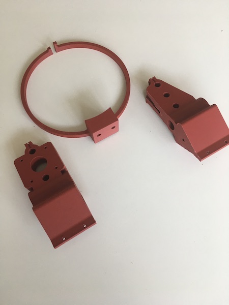
The results coming off the printer are excellent. The layers meld into one another beautifully, to the point where it’s not always obvious that the part was 3D printed.
The completed embroidery machine parts are shown below.
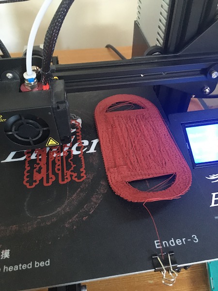
Although the parts turned out beautifully, one important lesson to learn was to be careful of smearing the brim layer. I wondered as the first layer went down whether I’d got the calibration right, since the bead seemed to be smearing on the bed cover. Everything was sticking ok, though, so I let it go. My previous experience had been with Ultimakers and glass beds, where the biggest problem had been getting the first layer to stick.
The result was that I ended up having to do a lot of very involved scraping after removing the parts to get the last of the very thin plastic layer off the bed cover. It didn’t help to heat the bed again, nor did it really help to cool it. I didn’t dare try any kind of solvent, so I just got out a sharp, flat putty knife and added some elbow grease. It was so awful in fact that I did some fairly serious damage to the cover and we’ll probably need to replace it. I’ll know for sure when the rover model finishes printing.
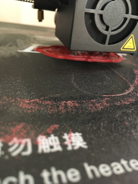
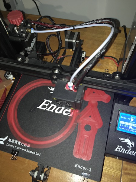
The Fusion360 slicer attempt never did work. The job started off moving way to quickly in a linear direction, so the extrusion wouldn’t stick. Then I tried putting a raft under the part, but although I got a nice looking raft (to the right of the printer head in the photo below), the long, linear extrusion didn’t stick to that either. Finally I gave up and went back to the Cura slicer, which started off with much more convoluted geometries and gave the extrusion the chance to stick (under the nozzle below).
Evenutally the print finished up with a good set of parts. There were seams I wasn’t expecting, but those sanded off ok.
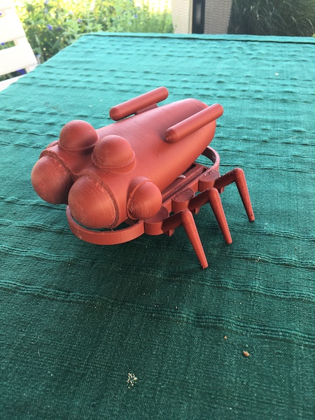
I glued the parts together with a hot glue gun, and here’s the result:
3D Scanning
The first of the 3D scanners we tried in the lab runs on an iPad (iSense). It worked really well for scanning a person sitting in a chair in a relatively uncluttered room, but it didn’t work at all on a glossy black steel spaceframe. Here’s the story of what we got up to.
A colleague’s bust.
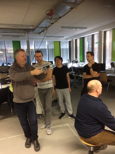
The method for scanning is simple. Modern software has come a long way since the days of yore when I had to make my own scanner using a laser pointer, linear motor and a webcam to scan a store mannequin (don’t ask). The first step in the process involves attaching a stereo camera to the back of an iPad, then starting the software. Next one selects a scene by tipping the iPad until the colour changes to red and yellow on the screen. Then it’s just a question of walking slowly around the model, rising and dipping to catch over- and underhangs, and stopping whenever the software needs to take a key frame, or loses the model. As long as the scene is relatively complex with large, slowly changing (with angle) geometries, the software can track the motion of the camera. With more difficult geometries, such as the race car frame below, the camera gets lost quickly.
A submarine hull
The first model I scanned was a simple closed shape: the mould of the hull of the existing Gymnobot robot submarine. Here it is in real life. The grey form in the foreground is the positive mould, while the black one in the background is the fibreglass top half of the hull.
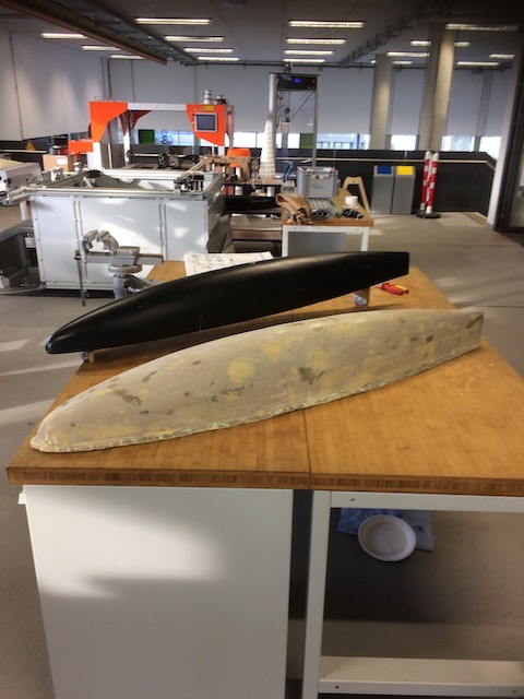
The scan worked out well, as can be seen in the top canvas on this page. The little element trailing the submarine hull is the edge of the vise in the picture above.
Racing Car Chassis
Spurred on by how easy that first scan was, I thought I’d try something more difficult. Our Formula Student team have had their chassis made, but the precision of the welding has not been verified yet. So here goes making a 3D scan of it as the first step in this quality control process.
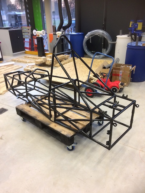
A first try at scanning this lovely, shiny, black frame was a total failure. The software failed even to recognise it. All of the other stuff around the car shows up in the scan, including the shiny blue steel tube on the little cart in the picture, but the car itself remains essentially invisible. The problem was therefore assumed to be the colour and glossy finish. To test whether this was indeed the problem, I covered elements of the frame with masking tape, then (to save tape) with blue paper towell.
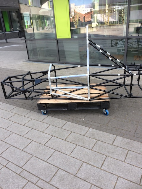
As shown in the canvas below, the scanner had a much easier time of it after this modification. The bars covered in blue paper are as obvious in the scan as the pallet on which the frame rests. The glossy black bars remain invisible.
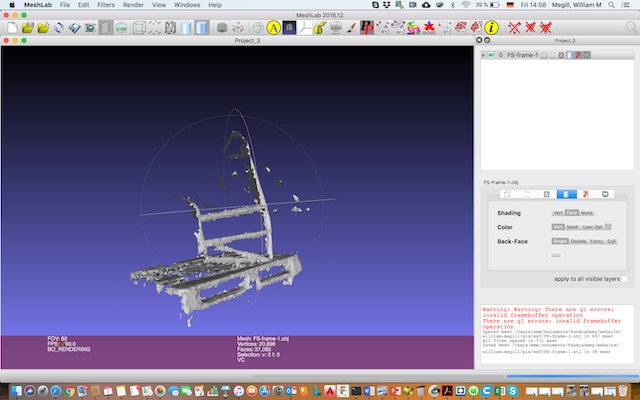
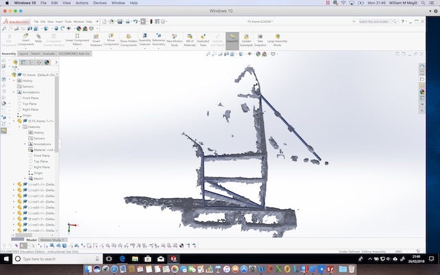
This scan is obviously not nearly precise enough to do much for the Formula Student team, but to start thinking about how they will approach the problem, I built a quick and dirty model of part of the frame in Solidworks and imported the scan as a part (having converted it from obj to stl using Meshlab as shown below).
The model is shown below in blue, poking through the scanned surface. Note the diagonal bar at the back of the car which lines up nicely through the splotches that correspond to the rings of masking tape wrapped around the bar of the real frame.
Saxophone
A change of equipment in 2019 made a big difference. This time, for some reason, I happened to have a saxophone in the car the day we were slotted to do the scanning. So we hung the sax from a pipe in the ceiling and scanned it with the handheld scanner, held in hand.
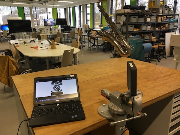
The 3D image that resulted was distorted, with wrap around errors so bad that it really wasn’t usable. The problem had two parts: one, the sax was moving a bit on its axis, and two, my ability to walk cleanly in a circle around the sax, holding the scanner steady and moving slowly, always keeping the sax in view at the same distance, was limited. So intead, we decided to ditch one of the variables. We clamped the scanner in a vise, then used the twisting elasticity in the hanging string to spin the sax around an axis through its centre of gravity.

The result was much better, as can be seen in the third image on this page
In each case the output is an OBJ file, which is just a list of vertices, normal vectors and faces, which can be read with any modelling package to create a model in space. Then, like I started to do with the Formula Student frame, one can fit a CAD model to the vertices to reverse engineer a numerical model for modification or simulation.
Group Assignment
Our week 6 group assignment can be found here.