8. Computer controlled machining
Make something big.....
CNC Mill
The CNC mill is a lovely machine. I’d long jealously watched people making fabulous stuff with it, so it was a real pleasure to learn to use it myself (despite some of the frustration that appears later in this week’s report).
The business end of the machine consists of a large flat bed with a heavy duty vacuum clamp system strong enough to suck through a 1/2” MDF board. Plywood or other materials to be cut are laid on the MDF, and the vacuum, which can be selectively applied to various regions of the bed using a set of buttons labelled with appropriate cartoons, holds them firmly. Small objects or porous materials like OSB have to be held additionally using traditional G-clamps, double-sided tape, or screws. The mill head and spindle are suspended above the bed on a cast iron traveller which rolls on high-precision rails laid along the sides of the bed. The mill head runs across the bed along rails mounted to the traveller, and the spindle moves up and down on rails mounted to the head.
Control of the machine is effected using a dedicated PC built into a steel container on wheels. A handheld remote control unit allows the machine to be used in manual mode. It is also possible to input G-code commands directly into the computer. Generally neither of these methods are used. Instead, one brings a DXF file on a USB stick, and creates the G-code from that using the CNC program on the computer.
The program user interface has several tabs. The ones that matter for our purposes are labelled “Control” and “Program”. The former contains all of the commands required to operate the bed remotely. It is from here also that the user can monitor the machines progress against the program which is created in the second tab.
Starting the machine
The power knob is low on the steel console. Several emergency stop buttons are located around the bed and on the console. Once the power is on, hit “reset” and “start”. The computer will come on in the usual Windows way.
The dust extractor is in the corner of the room. It needs to be started before cutting begins. It’s loud, so hold off until you’re completely ready. Two knife valves control which of the machines (mill or table saw) sees the full suction from the extractor. Control of these valves is effected using the switches mounted between the windows behind the table saw.
Once Windows fires up, start the program called CNC 4.0 and select the “Control” tab. The machine needs to be “homed”. There is a button on the right hand side of the screen (centre of mass symbol with two filled in quadrants). Be careful that nothing is in the way of the milling tool before clicking on the homing button. The machine will then send the spindle to the front right corner of the bed and calibrate its axes on the way.
The second most useful button on this toolbar is “get tool”. Clicking this will pop up a dialog box in which the number of the tool (1 to 6) can be entered. As soon as the enter key is hit, the machine will quickly return to the rack at the back of the bed and swap the current tool for the one selected. “0” will command the machine to select no tool at all.
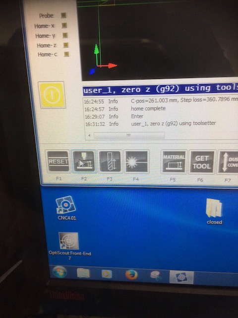
To zero and calibrate the z-axis, a special tool is used along with a subroutine in the control program. Move the mill head to somewhere away from the job, then drive it down until the tip of the tool is approximately 4cm from the bed. The calibration tool is kept in a holder on the top of the head. Place it under the tool, then select the F2 tool in the User toolbar. The head will travel slowly down. Place the calibrator on the bed directly below the tool and wait until the tool completely depresses the button on top. The machine will stop and return to a safe height after it has calibrated itself.
Next use the remote control to move the traveller out of the way so that the job can be secured on the bed. It’s easiest to line up the job with the front right corner of the bed, but if this is not practicable, or the vacuum isn’t sufficiently strong, then other installations are also good. Once the job is placed and vacuum clamped, the head can be driven back to the origin of the job. Two buttons on the control screen allow for the zero-ing of the x and y axes (remember that the orientation on the screen is effectively rotated 90 degrees to the orientation of the bed).
The third button of note is labelled “dust cover”. This raises or lowers the cylindrical cover over the cutting tool, ensuring that the dust extractor can generate the necessary suction to keep the working surface clean.
Speeds & Steps
The final step in preparing the machine for use is to set the speeds, stepovers and stepdowns. That will allow the machine to create the appropriate G-code. This is done for 2D machining from a Rhino file. When working from Fusion 360 in 3-D machining, then the cutting parameters are entered into the CAM part of that software and the G-code is generated there.
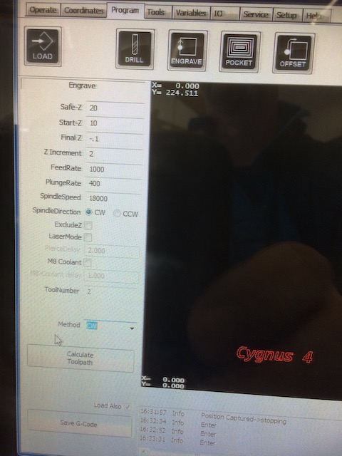
For the cuts described in this assignment, I used the standard cutting speeds and steps recommended by my instructor, as follows:
| Parameter | Value | Comments |
|---|---|---|
| Safe-Z | 20mm | This is the retract height, where the machine goes before travelling |
| Start-Z | 10mm | The starting height for the machine’s cutting pattern |
| Final-Z | -0.1mm | The bottom of the cut - when going right through, go 100um into the MDF board |
| Z-Increment | 2mm | The step down |
| FeedRate | 1000mm/min | This works well for chipboard |
| PlungeRate | 400mm/min | Slower than the feedrate, since the mill’s not really made for drilling |
| SpindleSpeed | 18000rpm | With one cutting tooth on the milling bit, this needs to be pretty much as fast as possible |
| SpindleDirection | CW | Rarely is this going to be anything else |
| ToolNumber | 2 | Whatever holder the desired tool is in |
| ToolDiameter | 6mm | Self explanatory |
| Method | CW | For inner cuts, use Inside CCW. For outer cuts, use CW |
For cuts not going all the way through, naturally I changed the depth of the Final-Z parameter. Otherwise these are the settings I used throughout this assignment. If they work, don’t mess with them!
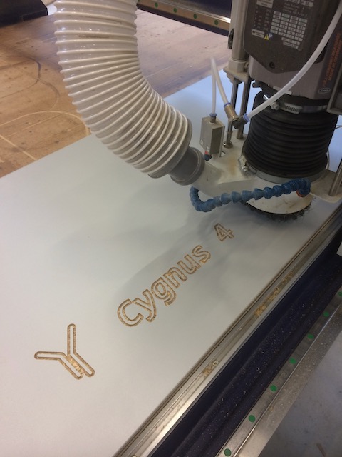
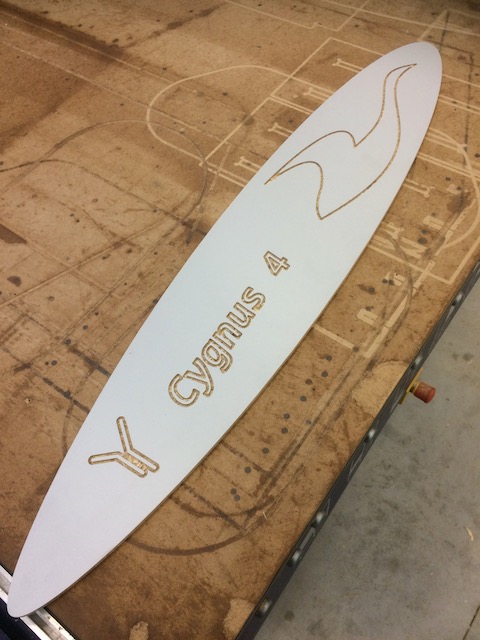
Test Part: Sub Museum Sign
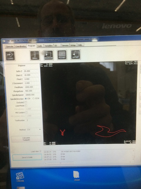
As a first test, I drew a simple 2D sign for the Submarine Museum to be cut out of a simple piece of scrap OSB we had lying around. The drawing was simple - just some text, the University logo and the outline of a flying swan, all done in Powerpoint. The file was then imported into Rhino, and the various lines were separated onto two layers, one for the engraving, and one for the outline to be cut right through. The curves on each layer were “joined” and then the file was exported in DXF format using the “R12 Lines & Arcs” option. That could be imported directly into the CNC machine’s control software.

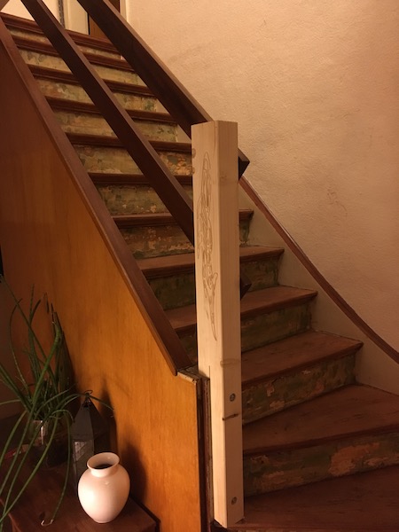
Engraving a Bannister Post
You’ll remember back in the laser cutting assignment, I made some inserts for the risers on the staircase in my home. Well now it’s time to replace the bannister of the same staircase. I’m a real fan of First Nations art, so I thought I’d make a drawing of my own, based on a traditional drawing of a salmon that I’d seen online. I think the original piece was Coast Salish, but I’m not sure any more and can’t find the original. Here’s my version of it, done in powerpoint:

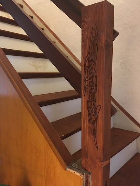
I imported the art into Rhino and used the same process as described above to create a toolpath for the big CNC mill. This time however, there was no cutout layer as the engraving is simply centered in the piece of wood.
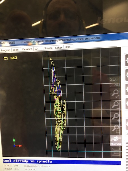
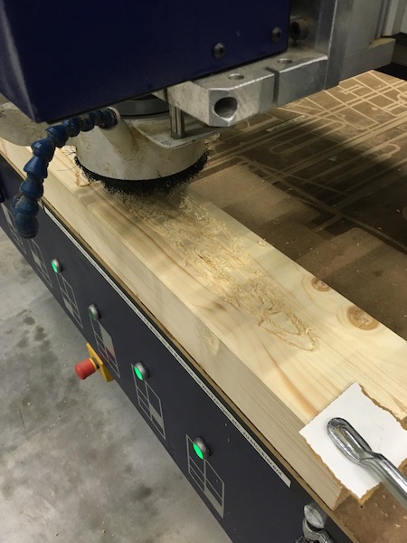
Once the toolpath is generated, then it’s just a question of zeroing and letting the CNC cutter do its magic.

The salmon installed at the foot of the stairs.
And then stained, and accompanied by the rose-covered risers:
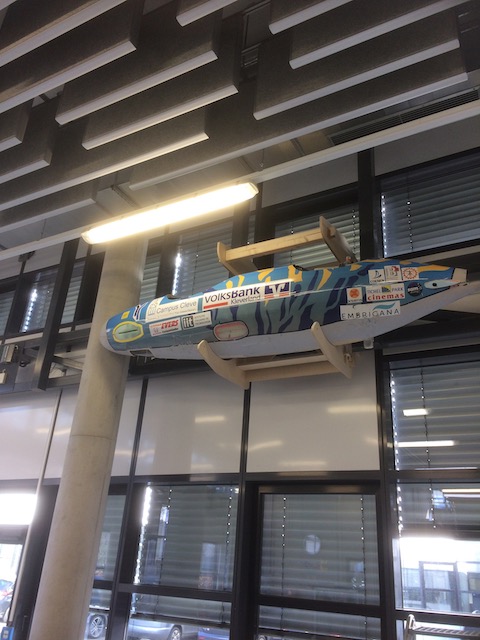
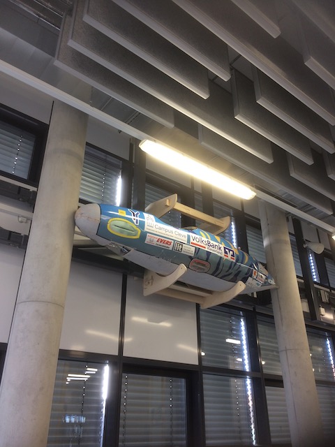
Making Something Big: Submarine Hanger
My students take part every year in a human-powered submarine race, either in Washington DC (odd numbered years) or in Gosport England (even numbered years). The submarines they build are about 3m long by about 70-80cm in diameter.

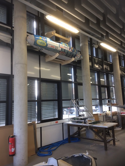
Even though they’re on wheels, they do take up a lot of room in the lab, and so a clever solution for storage space is needed. The girders along the outer walls of the lab (seen above the students’ heads and below the upper windows in the pic below) seem like they were designed to have submarines hung from them.
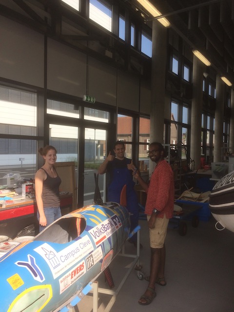
The idea came from a similar set-up I saw at the TU Delft, where they’d hung two of their submarines on a wall over their workspace. The submarines weigh about 75kg when empty.
Design
I was going to make the frames out of steel as Delft had, but taking this class has reawakened the carpenter in me, so here goes with a design made out of plywood. The first draft (in steel) was drawn up in OpenSCAD, using some parametric structure so that I could easily adjust the spacing.
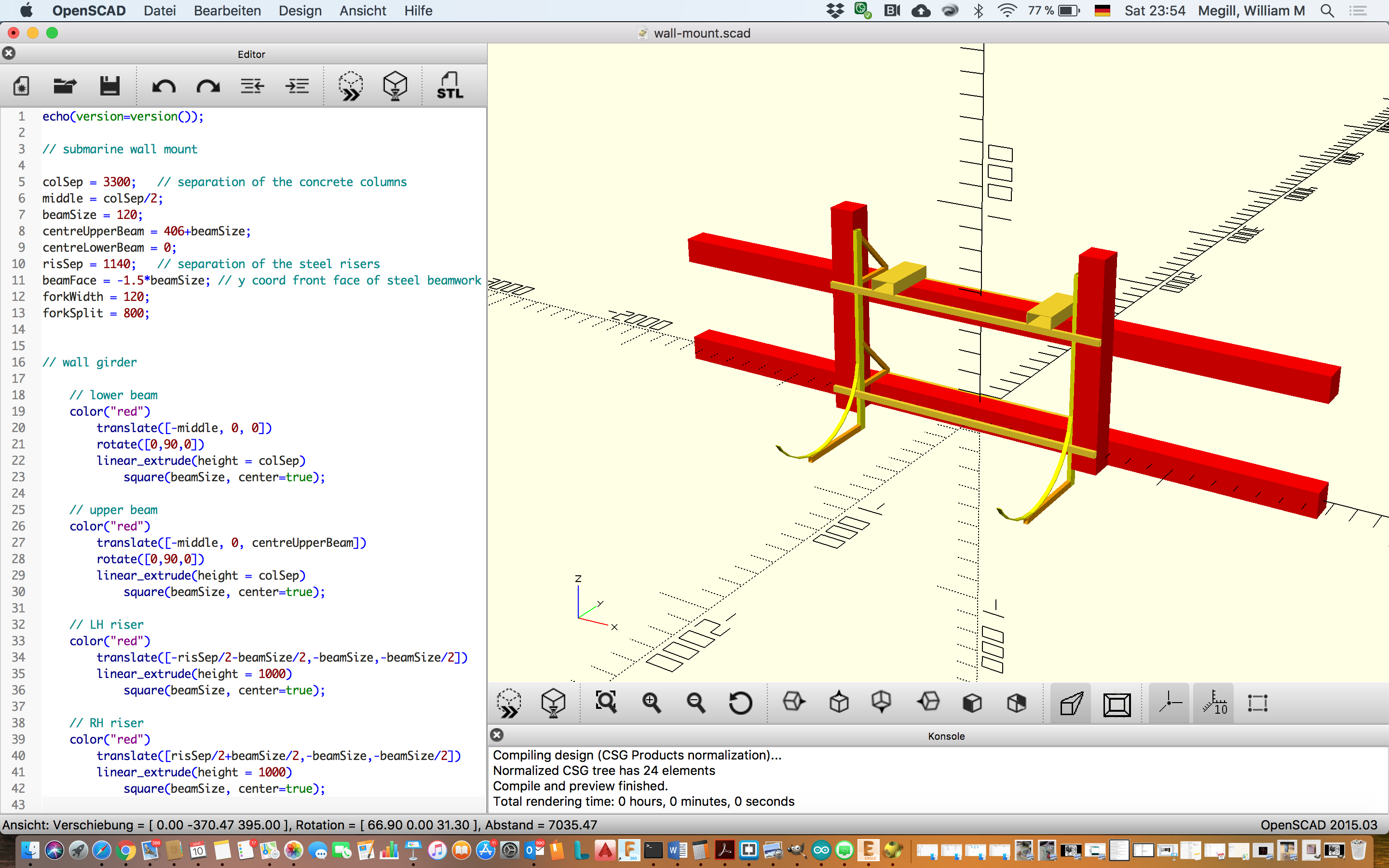
OpenSCAD works well for simple shapes, but for the kind of organic looking shape I wanted to do on the CNC mill, it didn’t make sense to fight through the mathematical representation, so I turned to SolidWorks instead. The final design looks like this:
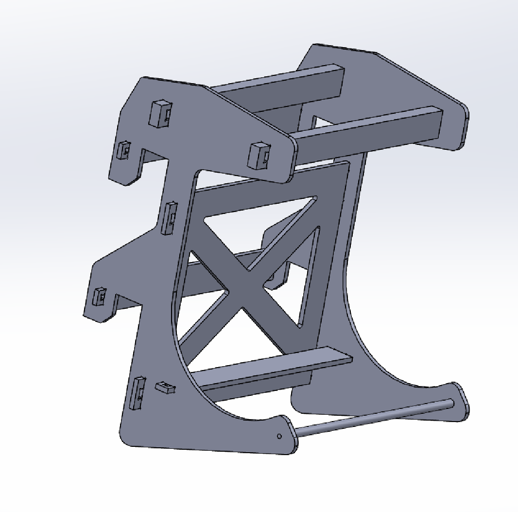
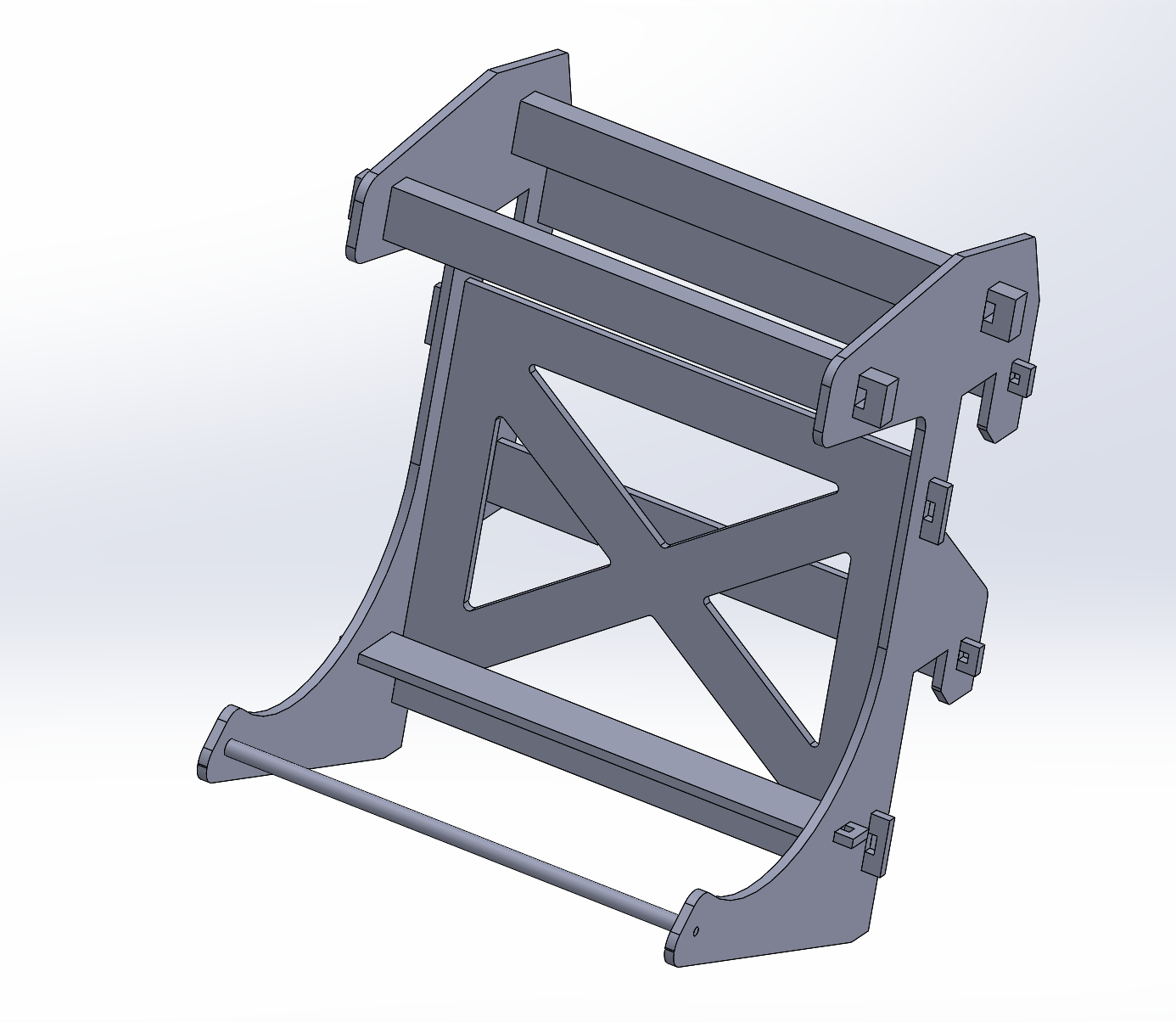
The design consists basically of two brackets which support the submarine on the one side, and hang snugly off the girders on the other. The cradles are curved under the submarine, with a raised lip on the outer edge to ensure that the sub doesn’t slip out during lifting or lowering (or indeed in during the time it’s on display). The back side of the brackets consists of two open square slots which fit snugly over the girders such that the weight of the submarine and frame is distributed over the tops of the two girders. The centre of mass will be out over the cradles, so the hanger will tend to rotate around the upper girder. The vertical side of the the bracket will stop that motion. I had some welcome feedback from my instructor about the width of the central riser section of the bracket, which I incorporated into the final design, shown on the right. I also shortened the bracket a bit vertically so that I could fit two of them on a 2,5m long plywood board.
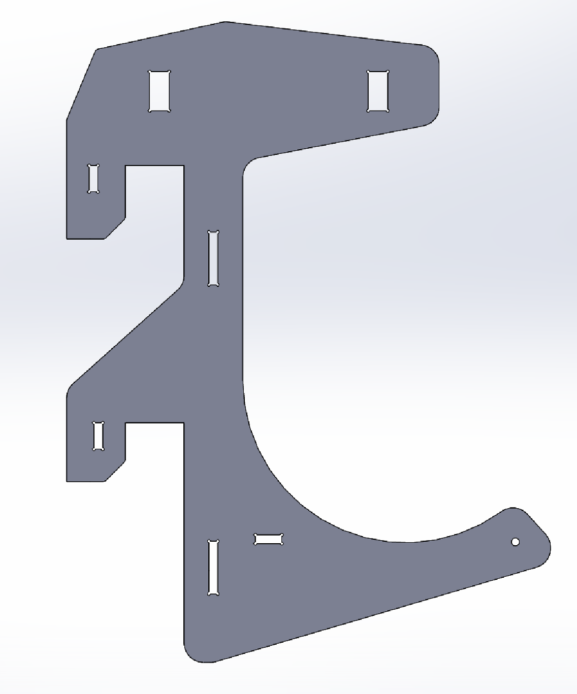

Rigidity of the frame is assured through the crossed members of the back panel. The whole panel is cut from a single sheet of plywood, which results in an even distribution of the loads. The back panel is attached to the brackets through the use of slots with keys.

Additional torque resistance is provided by the three smaller braces. These are also connected to the brackets using slots and keys. Note the 6mm diamter circular cutouts in the corners of all of the square holes. These are there to allow the tool some room to manoeuvre as it machines out the slot.

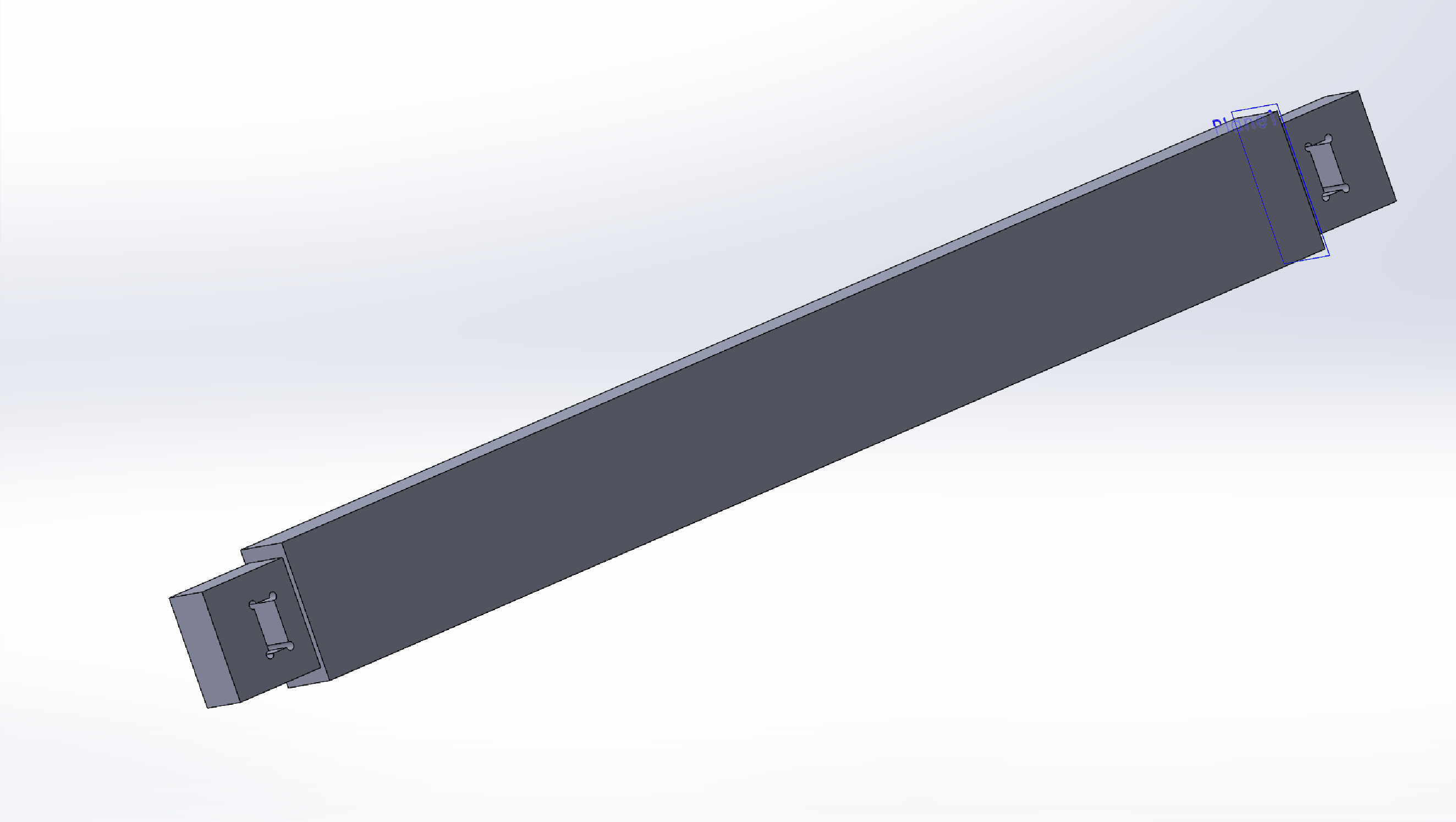
The hanger is designed to be lifted up or down from the girders using the university’s forklift truck. The overall combined weight of the unladen submarine and wooden frame will be about 85kg. This load is easily supported by two 2x4” beams. The forklift’s tines are usually set at 80cm separation distance. The frame is 89cm wide between the brackets, ensuring that the forks are very near (without touching) the brackets, in order to minimise the bending load on the beams. The beams are furthermore connected to the brackets using the slot and key design incorporated for the other elements above. In order to distribute the load more evenly over the 2x4” beam, the ends are milled symmetrically, which required a few extra passes with the mill and some careful alignment of the workpiece during set up.
The last piece is a dowel for the lower front side. Mostly this part is cosmetic, and serves as a place to hang a sign from, but it also plays a minor role in ensuring that the cantilevered lower braces don’t splay apart. During lifting and lowering, the dowel will also serve as a place for fastening straps to keep the submarine in place.

We don’t have a CNC lathe available in the FabLab, so I had to make this piece by hand on the manual lathe in my workshop. I didn’t have a wooden dowel available, so I used a bar of PVC instead.
From CAD to CAM
The process required to create the toolpaths for the CNC machine from the SolidWorks design was relatively clear and straightforward:
- Export the files from SolidWorks in 2D dxf format
- Import the DXF files into Rhino
- Select and “join” the curves
- Arrange the various parts to be cut to make best use of the plywood sheet
- Split the small internal cuts and large external ones onto separate layers.
- Export the file from Rhino as DXF using the “R12 Lines & Arcs” option
- Import into the CNC program on the mill control computer
The built-in CNC program generates the g-code in the background - Cut out the internal layer as described in the CNC section above
- Cut out the external layer
- Remove the finished parts from the mill
- Clean up and go for lunch
Dinner came and went.
It was only after the pizza had landed face down on the floor and been consequently binned that the software bug finally presented itself. Somewhere in Rhino, something gets corrupted, and the DXF export function generates erroneous code. Curves are separated and segments are scattered seemingly randomly around the screen when the file is loaded in the CNC control program.
The workaround is apparently simple:
- Complete all steps above to #5, then:
- Select all and copy
- Open a new instance of Rhino
- Paste the parts into the new instance.
The Rhino export for the first plywood sheet looked like this:
Manufacture
Once I added those steps into the process, the whole thing worked like a charm, and I could start cutting the shapes out of the 1,25 x 2,5 m bit of 18mm thick plywood board I was provided. Cutting started with the small inclusions:
… and finished two hours later with fully cut out parts, ready for assembly.
The process was repeated with a second board. Parts here were the back of the frame, one more stringer and the locking pegs. To ensure that these latter parts didn’t fly around during manufacture, the external cuts were stopped 1mm from the table, and when the machine had finished the cutting pattern, we taped up the top of the little blocks with masking tape, then ran the cutting pattern again to cut through the tape and the leftover plywood at the bottom of each cut.
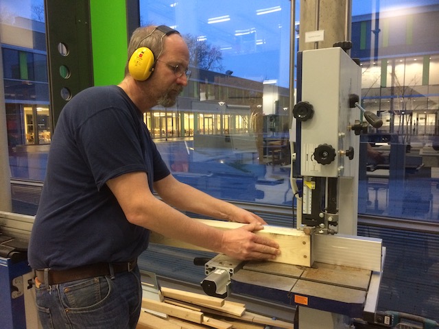
The final manufacturing step was to make the two top beams. I decided not to use plywood for these, as I was worried about delamination, since the beams are to be loaded on the thin side, and will have to take repeated hits from a forklift truck’s tines. I opted instead for a pair of trusty 2x4’s. They don’t make 2” x 4” cuts in Germany, so a 6cm x 10cm bit of pine was purchased instead.
There are times when automation just isn’t up to the task. It proved impracticable to clamp the slightly warped 2x4 to the mill bed (even screws wouldn’t have solved the problem, as the warp would simply have bent the MDF bed). So instead, I dusted off my old wood shop skills and fired up the band saw. Four cuts at each end, and voila.
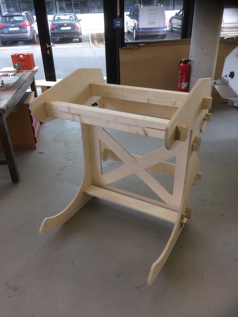
Assembly
Assembly was straightforward. Some quick work with a hammer, and a few additional fillet cuts with the bandsaw put the whole thing together nicely. Some of the fits were pretty tight, so I used a spare bit of 2x4 as a stress distributor when hammering. Also the plywood tended to lift around some of the joints as the perpendicular piece moved through, so I used the block to hammer directly on the lifting parts, which put them back into place.
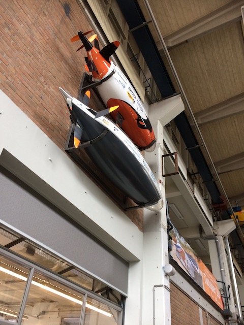
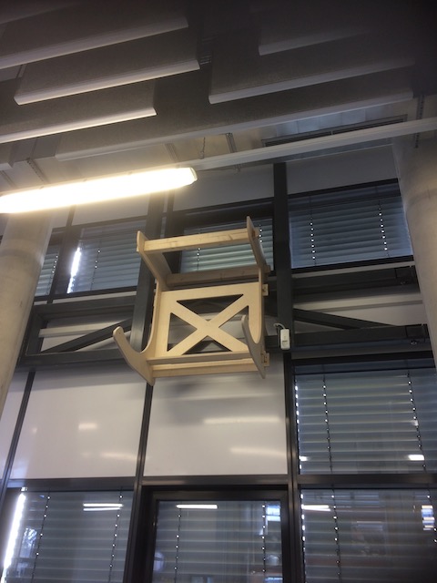
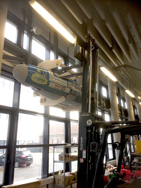
Installation
The adventure of getting the submarine up onto the wall involved BIG stuff indeed. We had a few adventures with the forklift getting the frame up onto the girders, but we got there in the end, and our submarine Rivershark looks fabulous in her new home on the wall.
Scuba Tank Cart
We have a challenge in the lab, in that the University’s safety people are struggling with how to fit our diving activities into the strict rules about the storage of gas cylinders. The problem boils down to whether a cylinder is “in active use”, and therefore permitted to be in a lab, or “in storage”, in which case it must be committed to a dedicated storage facility. The rule is designed to handle large cylinders that might be found in a chemistry lab, but it doesn’t work well for scuba tanks (which after all aren’t regularly found in the German university environment, at least not in North-Rhein-Westphalia.)
The compromise we’ve worked out with the authorities is to formally demonstrate that the cylinders are formally “in use” (which is the truth - we just have to make it obvious). So what this means is that the cylinders have to be arranged in a cart on wheels which prevents them from falling over.
The Design
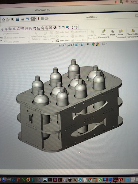
I’ve opted for the castellated plywood approach in my design. Keeping with the FabAcademy tradition, I’ll avoid nails, screws and glue (for now - the weight of the tanks and the rough handling my require some fasteners later. We’ll see.)
On digging further into the SolidWorks help files, I discovered a way to do parametric design directly in the program, without having to involve an external Excel spreadsheet, which had previously defeated me, since I was trying to do Windows things on a Mac… It’s a bit fiddly, but it works ok, at least for the initial laying out of the elements. The trick is in the use of the Equations tool, combined with the linear sketch pattern tool. It’s not quite the easy parametric design approach of OpenSCAD, but it works.
I started by drawing a dive cylinder. We have two sizes that need to be transported in this cart, one of 3L capacity and one of 5L. The tank consists of a cylindrical body, squashed hemispherical base and a shoulder/neck at the top. I drew the 5L tank first, with all sizes referenced to the diameter of the cylinder. I then saved a copy, which I made into the 3L tank simply by changing the diameter of the cylinder. In retrospect, it would have been even easier to do by drawing the radial section in one plane, then revolving the whole thing at once.
Once I had all of the cylinders available, I started on the top of the cart. The first step was to set out the overall dimensions of the cart, which were done parametrically based on the diameters of the cylinders and a set width of plywood between the edges of the cylinder holes and the sides of the top. To set the parametric size, I first created a rectangle in the usual way and accepted it, then used the Smart Dimension tool to update the size of the rectangle. Because I was going to round off the corners, I added two construction lines between the centres of the rectangle’s opposite sides. Then I used the Smart Dimension tool to set the lengths of the construction lines (and thereby the overall shape.) This can be done parametrically by writing in an equation into the Smart Dimension pop-up box. Quotes are used to create new parameter names.
The parameters are all to be found in the Tools:Equation command. They can be exported as a text file:

To cut a long story short, here’s what the beast will look like.
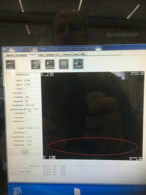
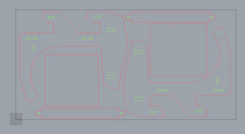
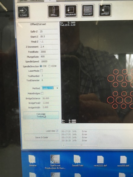
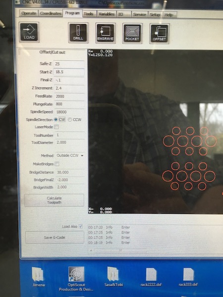
Once the cart was completed in SolidWorks, I exported each of the parts as a DXF file, then imported them into Rhino to arrange them on the plywood board for cutting. I used the same process as before, arranging the internal cut-outs (the fish) on one layer, and the external cuts for each part on a second layer, to keep as much connection to the bed of the machine as possible while it did its cutting.
The CNC settings were as follows (the cutouts for the first layer are shown in red):
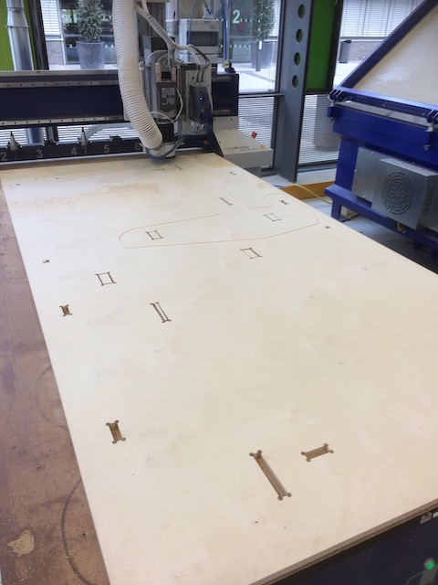
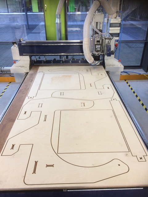
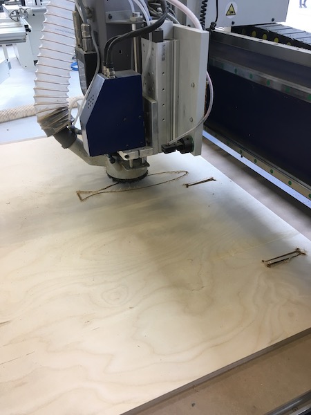
The CNC machine getting started:
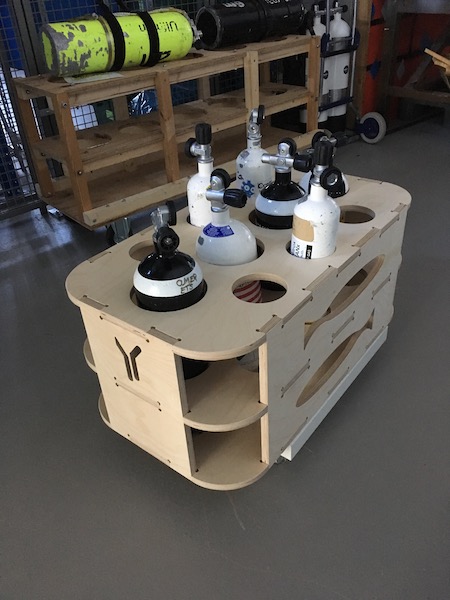
And this is the cart in nearly completed state. The only thing missing is the casters. In the background is the first cart we made in the lab using the available hand tools. The CNC machine does a much nicer job!
Group Assignment
Here is the link to our group assignment
Files
I’ve unfortunately lost the earlier design files (for the museum sign and submarine hanger), but here are the more recent ones:
Hopefully the CAD files are ok. I no longer have access to SolidWorks to verify!