9. Embedded programming
My own board
Moving the smoke around the electronics…
This week’s objective was a simple one: Upload some code to the Hello World board and have it do something. Funny how “simple” doesn’t always work out that way.
I’ll start with an Arduino Uno and the Arduino IDE, since they’re both so simple to use.
Fuses and Padlocks
The Hello World board I made back in Exercise 6 was readied for use. I very carefully mapped the pins from the FabISP programmer onto the pins of the HW board, then connected everything as appropriate. I confirmed using the Arduino IDE that the FabISP was properly connected to the Mac, and the LED that started flashing on the HW board confirmed that it, too, was still happily in the state I left it in at the end of Exercise 6.
It was now time to reprogram it to do something more exciting. First step was to burn the fuses to set up the clock and data transfer. I used www.engbedded.com/fusecalc to work out the correct settings for the attiny44. The settings we selected for the chip are as below:
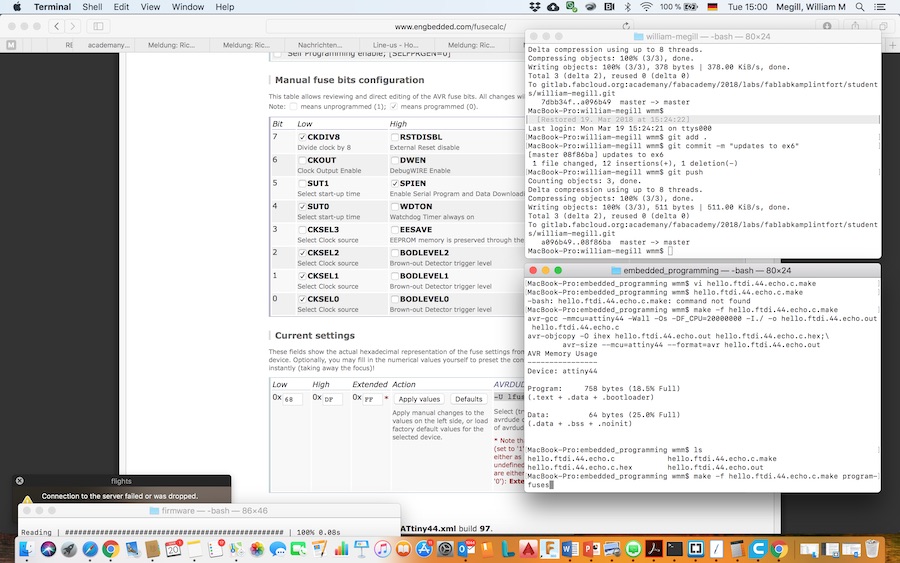
I then modifed the makefile with the settings indicated (68-DF-FF) and ran the make command with the program-usbtiny option. The board confirmed that the fuses had been successfully set.
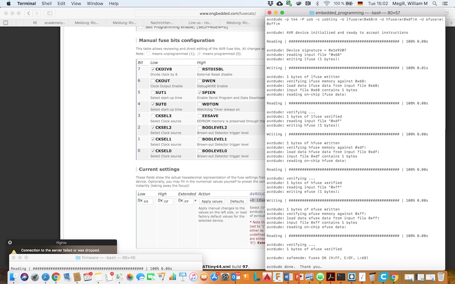
The trouble began as we tried to upload the c code. The HW board would no longer respond to anything we tried to send it. Somehow I bricked the chip. Some hunting on the net brought out the Dragon board, but after looking at what would be required there (a high-voltage reset!), I decided it would be easier to replace the attiny chip.
Unfortunately the already fragile board did not survive the operation, so everything went into the trash, and it was time to see how much I’d learned in Exercise 6.
A new board
Back (literally) to the drawing board. I figured since I had to make a new board, might as well do something interesting this time. So taking inspiration from my FabAcademy classmate and his creative “Millenium Falcon” board, I thought I’d have a go at making a swan in honour of our local castle.

Die Schwanenburg by Maarten Takens
Design
On to Eagle. The circuit design starts with the ATtiny84. The datasheet can be found here. All the info a guy could ever want about this little fourteen-footed beast is included there. The bit that interested me most was the pin-out:

The function of the pins and some handy advice is provided in the next couple of pages following the pintout diagram. Taking that advice into account, I designed a circuit which includes the following elements:
- To enable the board as a programmer, a 20MHz crystal was connected between pins 2 & 3. Capacitors were added between either side of the crystal and ground to smooth out any spikes in the timing circuit.
- The MISO, MOSI, SCK and RST pins are connected along with VCC and GND to the usual six pin (2x3) ISP header.
- The board is also set up for serial connection to another device. For this I used a six pin linear header with VCC, GND, TX and RX.
- RX and TX were connected to pins 12 and 13, respectively, of the ATtiny44.
- For debugging purposes (and to make it exciting when it’s operating), I connected three LEDs: one to pin 6 just as an indicator from the program on the chip, one to pin 8 to signal when the MOSI line is active, and one to pin 8 (MISO). The LEDs were placed in series with 500Ω resistors to ensure the current draw was appropriate.
- A pull-up resistor was added to keep the RST pin from accidentally going low and clearing the chip’s memory.
- I added a pushbutton between Vcc and pin 10, with a resistor to ground. When the switch is closed, pin 10 goes high, and the resistor ensures that the pin goes low when the button is released.
- A capacitor was added between Vcc and GND as a low-pass filter to smoothe out any stray noise signals on the power supply to the microcontroller.
- Two zero-Ohm resistors were added for jumps over the traces on the board.
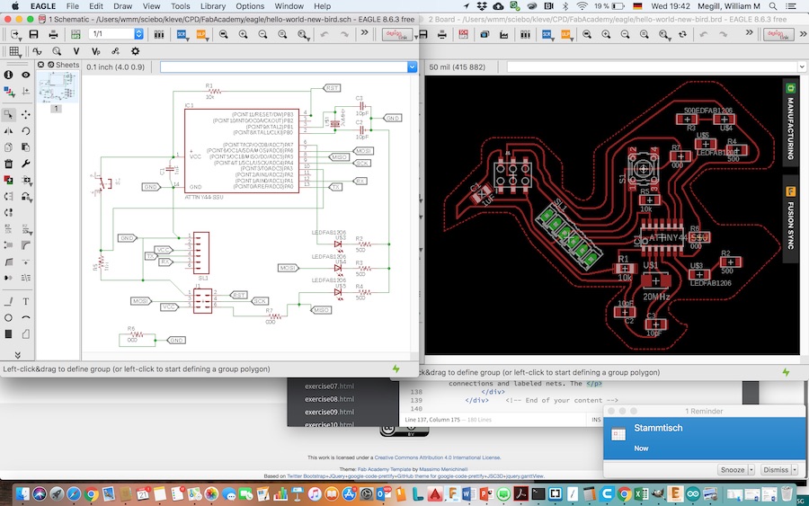
The schematic (shown below) is a combination of direct connections and labeled nets. I placed the elements on the new board layout in a geometry reminiscent of a bird (I tried for swan, but it’s ended up looking more like a crow). I had to try several arrangements to finally connect all of the nets, and I had to use two zero ohm resistors. Once the design was completed, I ran the ULP “cmd-change-brd-width” to increase the width of all of the traces to 16mil (0.4mm). That required a bit more rearranging (and the second zero ohm resistor). The final design looks like this:
Manufacture
The milling of the board proceeded in the same way as before, except that I did most of it independently this time. Remembering that the Mac version of Eagle is buggy, I took the schematic and board files to a PC and exported the board as a monochrome PNG image with 1500DPI resolution.
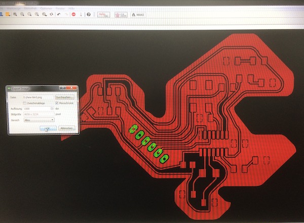
The board image was imported into GIMP, where I split the inside from the outside (by lassoing the insides and deleting everything). I had to tidy up the edges a bit to ensure the cutting would be complete. Finally I ran the two files through fabmodules.org. The settings for the traces were as follows:
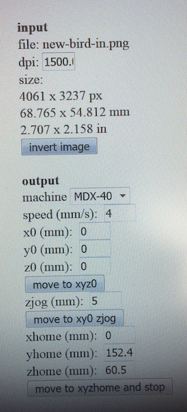
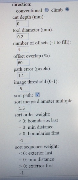
The Roland mill was straightforward to set up. First stick a fresh PC board to a stiff bit of MDF with double sided tape. Then clamp the board to the mill bed. Next move the head to the bottom left hand corner of the desired cutting area. Set the XY zero. Then move diagonally to the middle of the cutout and set the Z zero using the calibration device. That part was new for me, but simple - place the device below the end mill, then use the second menu entry to “set Z with calibration device”. The machine found its Z. Then I started the spindle (10000 RPM) and dropped the mill to the Z zero. To dig into the board, I drove it 0.08mm into the copper. Finally I started the cut.
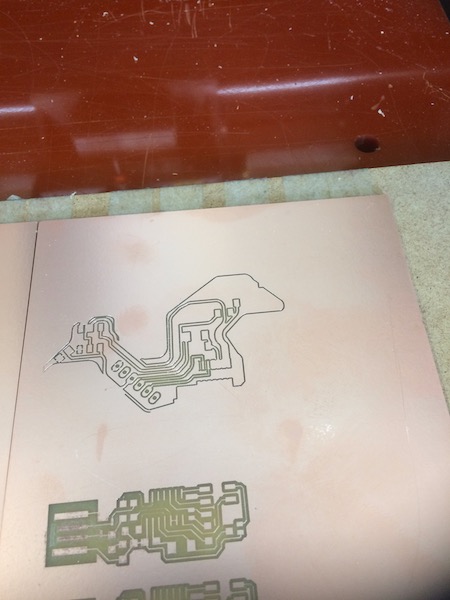
Partway through the cut, I hit “VIEW” to see how it was getting on. The machine interrupted its work and spat the bed out to the edge of the table. A quick vacuuming revealed the photo below. After inspection, a longer press of the “VIEW” button returns the machine to work.
Once the traces had been cut, the outline could be milled. For this I switched to the 2mm end mill, then ran the outline image through mods with a 1mm/s speed and drill size 0.5mm. (In retrospect, I should have gone back to the image and made it a bit larger, as the edges of the board ended up too close to the traces).
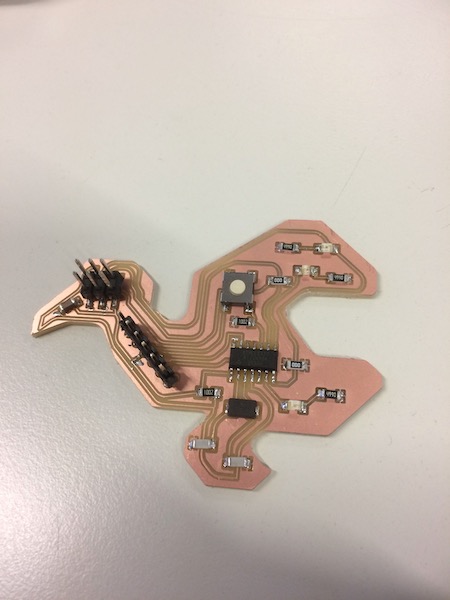
After soldering all of the components in place (we ran out of attiny44’s, so I used an attiny84 instead. The only difference apparently is the size of the onboard memory), the final assembled board looks like this:
Connecting the board
Counting the pins on the bird board from the beak toward the neck along the ventral row and back along the dorsal row.
| Line | BirdBoard | AtTiny | Arduino Uno |
|---|---|---|---|
| GND | Pin 1 | Pin 14 | GND |
| MOSI | Pin 2 | Pin 7 | Pin D11 |
| Vcc | Pin 3 | Pin 1 | Vcc |
| MISO | Pin 4 | Pin 8 | Pin D12 |
| SCK | Pin 5 | Pin 9 | Pin D13 |
| RST | Pin 6 | Pin 4 | Pin D10 |
Flashing the fuses
After successfully completing the smoke test, we used the hello.ftdi.44.make file to set the fuses. This time we used the defaults provided in Neil’s example. I made copies of the .make and .c files, renaming them to reflect the change to the attiny84. I also had to update the code in the .make file (see green boxes).
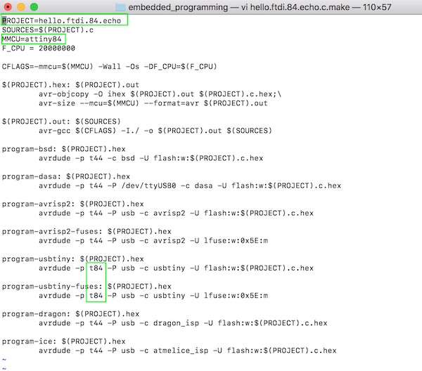
I compiled the new code and uploaded the hello.world.echo program to the board. The first pass through the make file, with program-usbtiny-fuses set the fuses properly.
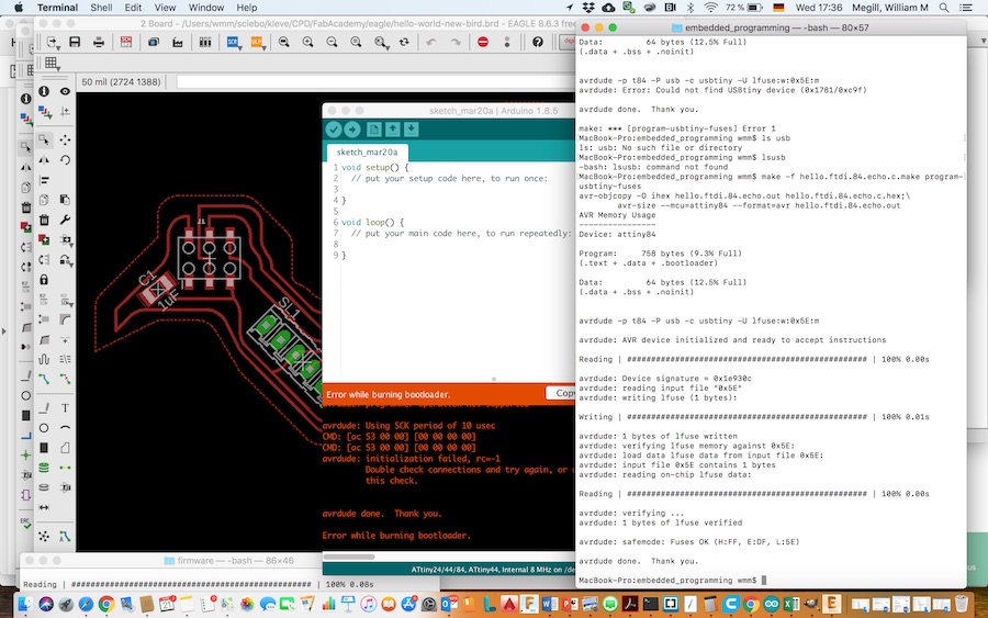
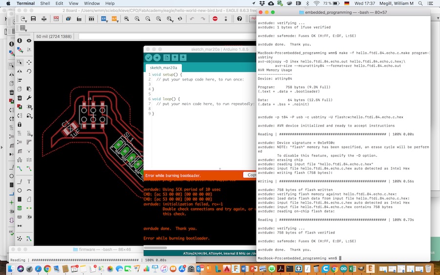
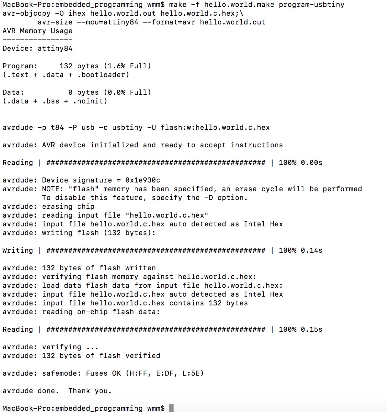
Then, with teeth clenched and fingers crossed, I ran the make program again (make -f hello.ftdi.84.echo.c.make program-usbtiny) to upload the code to the board. To our combined relief, it “just worked.”
Coding in C
As suggested in lecture, the starting point for my foray into the coding world was somebody else’s example code. I chose the hello.ftdi.44.echo.c code provided by Neil in the class notes. This compiled no problem and uploaded directly to the board, with the success indicated below.
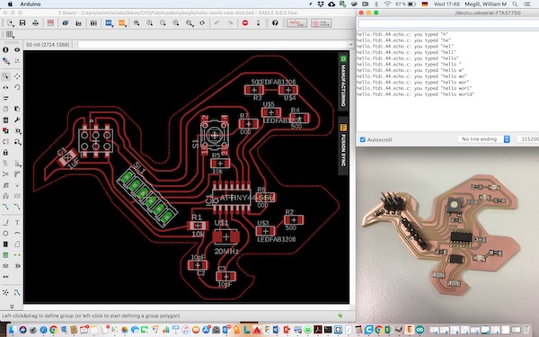
Having confirmed that the chip would receive the compiled code and respond to communications from the computer, I then looked to take the example program apart and write something that could operate the elements I’d built into the hardware, namely 3 LEDs and a pushbutton switch. The code I used is shown below.
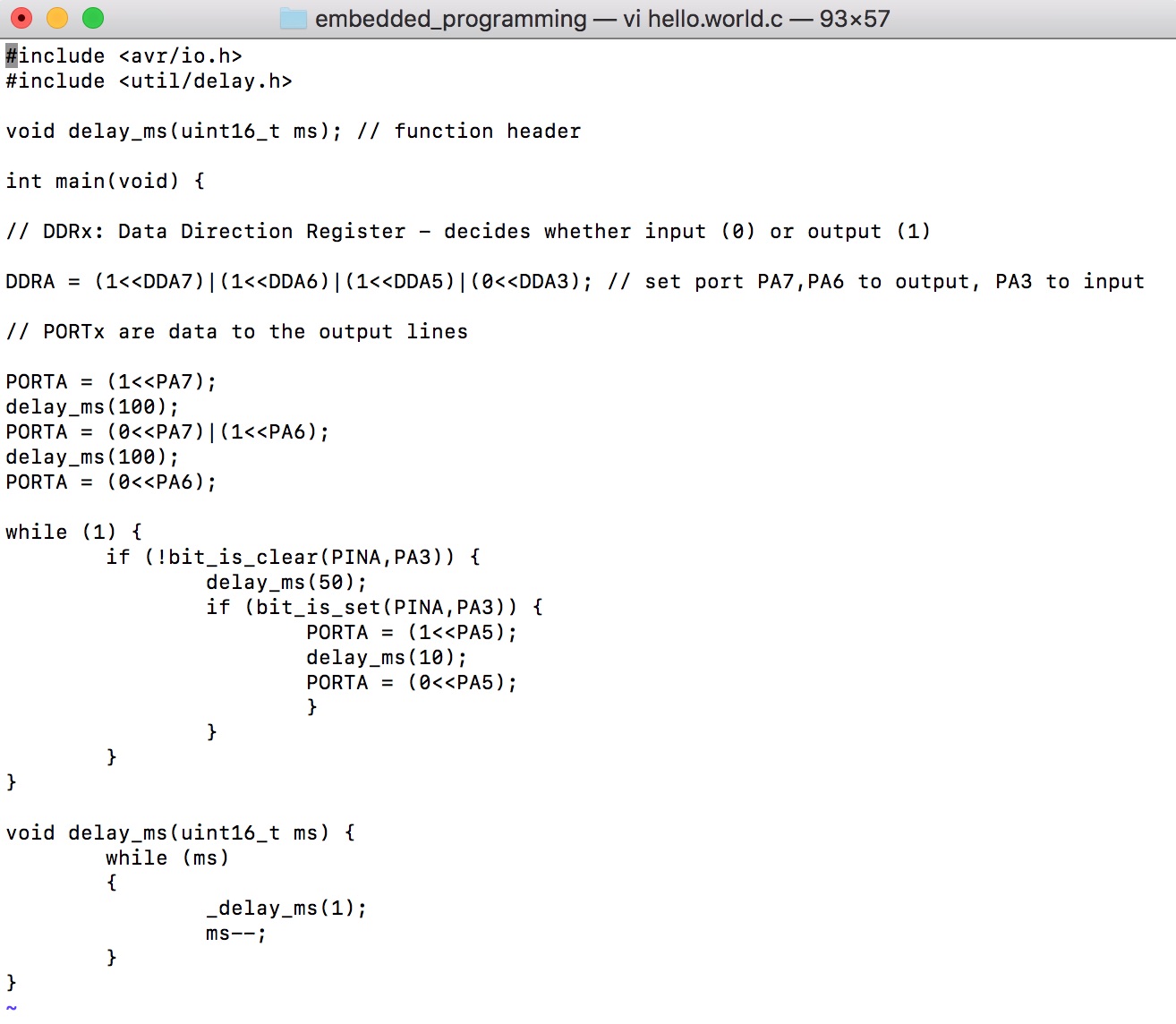
The first include statement enables the AVR’s communications capabilities and the second provides some simple utilities for making delay loops. Because this is C, the next line is the function header which is required when the function definitions follow the main program block. The program begins at int main(void).
Looking through the datasheet, I’m not (yet) taking advantage of all that the ATtiny84 can do, but the bit that I’m most interested in is input/output so that I can use a program (sketch) on the board to do something useful. I found the information I need in section 10, starting on page 55. There are three registers on an AVR tiny 84. Each register is 8 bits in size. The DDxn registers control the flow of information, (0) for input or (1) for output, of each of the microcontroller’s pins. The pins are gathered into two PORTS, labelled “P” for port and “A” or “B” for the two ports, as in the diagram below. The PORTx register sets the value of the pins when they’re set by the DDxn register as outputs. The PINx register reads the value of the pins regardless of whether they’re configured for input or output.
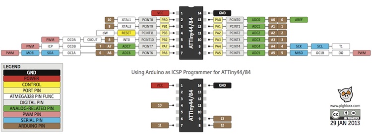
In my pcb layout, I used pins 6 (PA7), 7 (PA6) and 8 (PA5) for the LEDs and pin 10 (PA3) for the switch. These are the bitwise assignments in the next line. DDA7 corresponds to PA7, etc.
To write data to the pins, one uses the PORTx register. The register is again set bitwise for clarity, so the next block of code flashes the LED connected to PA7 once, then immediately flashes the LED connected to PA6. The function delay_ms, defined at the end of the code, provides a millisecond counter.
The while loop is used to read the state of the pushbutton. While(1) is always true, so the program is running in an infinite loop. The if statement triggers when the button is pressed. The delay and the second if statement are used to deal with the “switch bounce” which occurs as the contacts make initial intermittent contact when the pushbutton is pressed. The rest of the while loop flashes the third LED.
The code compiled and uploaded fine.
The following video demonstrates the code running.
Coding in Arduino
The Arduino IDE makes the programming easier by removing the compiler commands from around the main code. There are two default subroutines provided in the IDE. The first one, called “setup”, runs only once, as the device is first powered up. The second one, called “loop”, runs forever until the device is powered off.
The ports have different names in Arduino than they had in C. The LEDs now are connected to Arduino “pins” 5,6,7 and the pushbutton to pin 3. The data directionality is set, as in the C program, with statements at the start of the code (in the setup subroutine). Here the syntax is pinMode(x,INPUT|OUTPUT).
The LEDs are set to flash using digitalWrite(x,HIGH|LOW) and the delay() function. Then the reading of the pushbutton is done in the infinite loop() subroutine, again with a switch bounce defense.
The Arduino code is shown below, along with the port labelling figure again for reference.
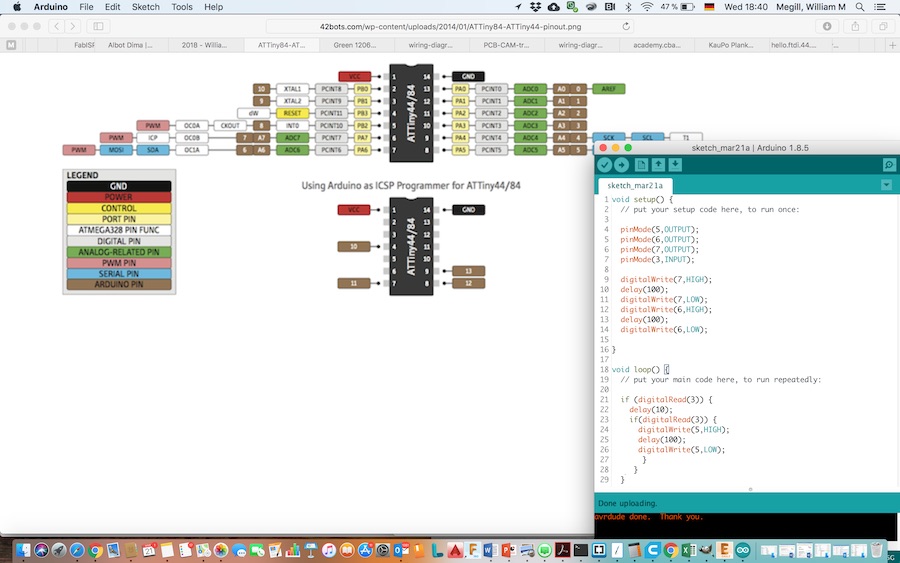
The Arduino IDE needs to be set up to work with the FabISP. The settings are in the Tools menu, shown below. The board is programmed using the “Upload using Programmer” option in the Sketch menu, as shown below.
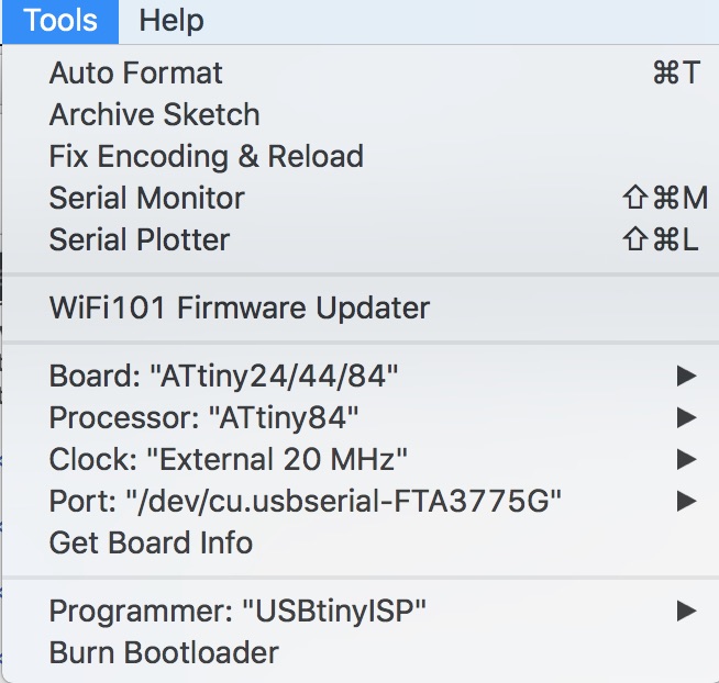
The code loads easily, and the video below shows the arduino version of the code running on the chip (note the longer delay on the green LED).
Downloads
Group Assignment
Our group assignment page can be found here.