12. Output devices
The coronavirus quarantine caused a lot of upheaval in the FabAcademy schedule this semester, so this week’s activities got done a little out of the usual order, and many of them before they were covered in class.
The first couple of sections here are about just making the output devices work with the Arduino, and so are based on the example code available in the Arduino library. In the later sections, I’ll use the servos and display screen in combination with some input devices to do something interesting.
Arduino vs Servo Motor
There’s a servo library and example in the Arduino examples library. All that’s required is to wire up a servo to the appropriate pins, as follows:
- Red -> VCC
- Brown -> GND
- Orange -> Pin 9
And then to run the Sweep.ino example by Scott Fitzgerald:
#include <Servo.h>

Servo myservo;  // create servo object to control a servo

int pos = 0;    // variable to store the servo position

void setup() {
  myservo.attach(9);  // attaches the servo on pin 9 to the servo object
}

void loop() {
  for (pos = 0; pos <= 180; pos += 5) { // goes from 0 degrees to 180 degrees
    // in steps of 1 degree
    myservo.write(pos);              // tell servo to go to position in variable 'pos'
    delay(15);                       // waits 15ms for the servo to reach the position
  }
  for (pos = 180; pos >= 0; pos -= 5) { // goes from 180 degrees to 0 degrees
    myservo.write(pos);              // tell servo to go to position in variable 'pos'
    delay(15);                       // waits 15ms for the servo to reach the position
  }
}
The Arduino sketch is available here.
And the servo oscillates back and forth between 0 and nearly 180 degrees.
Arduino and the LCD Screen
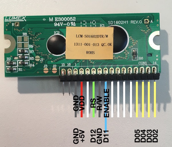
What looked like a challenge turned out to be made super easy by the folks who wrote the Arduino IDE libraries… Following the instructions in the commented section of the library, I wired up the LCD to the Arduino, then modified the code slightly and ran it to generate a two line message.
The wiring was straightforward:
- LCD RS pin to digital pin 12
- LCD Enable pin to digital pin 11
- LCD D4 pin to digital pin 5
- LCD D5 pin to digital pin 4
- LCD D6 pin to digital pin 3
- LCD D7 pin to digital pin 2
- LCD R/W pin to ground
- LCD VSS pin to ground
- LCD VCC pin to 5V
- 10K potentiometer:
- ends to +5V and ground
- wiper to LCD VO pin (pin 3)
The datasheet is here. To convert the datasheet to the reality on the bench, I took and edited the following photo:
Here’s the code that generated that message, based on the original Arduino example code by Mellis, Fried, Igoe and Guadalupi :
// include the library code:
#include <LiquidCrystal.h>

// initialize the library by associating any needed LCD interface pin
// with the arduino pin number it is connected to
const int rs = 12, en = 11, d4 = 5, d5 = 4, d6 = 3, d7 = 2;
LiquidCrystal lcd(rs, en, d4, d5, d6, d7);
char str[16] = "Quarantine4Life!";

void setup() {
  // set up the LCD's number of columns and rows:
  lcd.begin(16, 2);
  // Print a message to the LCD.
  lcd.print("FabLab@Home 2020");
}

void loop() {

  // set the cursor to column i, line 1
  // (note: line 1 is the second row, since counting begins with 0):

  for (int i = 0; i< 16; i++) {
    lcd.setCursor(i, 1);
    lcd.print(str[i]);
    delay(250);
    }

   // erase the second line

   for (int i = 0; i < 16; i++) {
    lcd.setCursor(i,1);
    lcd.print(" ");
    delay(100);

   }
}
The Arduino sketch is available here.
Self Made Servo Controller
For my final project, I’m going to need a motor controller board that can move three servos to control the sweep and heave of the shoulder, and the flexing of the elbow. It would also be good to have some feedback from the tip of the leg.
Electronic Design
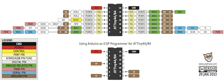
A single AtTiny84 on each leg should be enough to drive the servos with one pin each, read the microswitch on the footpad, and communicate via some kind of simple bus with the rest of the robot.
The pinout for the AtTiny84 is shown here:
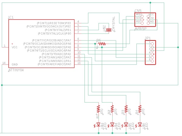
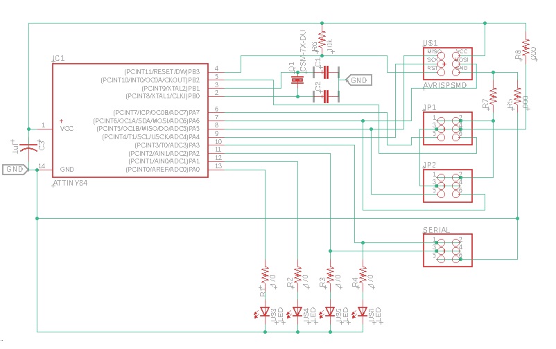
The wiring diagram for one leg looks like this:

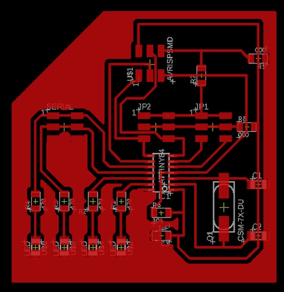
In Eagle, the first prototype looks like this:
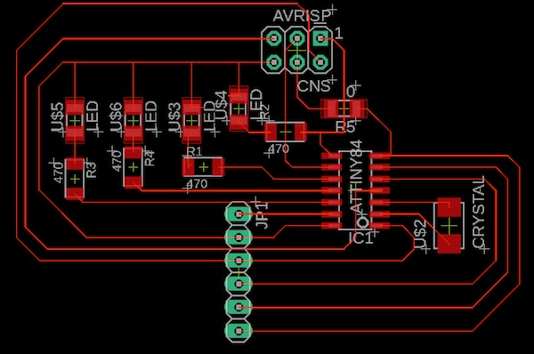
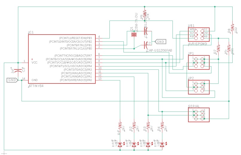
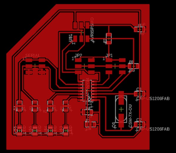
After discussion with the tutor, I made a few revisions. The new board looks like this:
After one more set of discussions, this time about the LEDs (with higher valued resistors to cut the current flowing) running from Vcc to the pins instead of the other way around, and some minor adjustments to width of the traces (which is done with the ULP called cmd-change-brd-width - trace width of 16mil is good) and the isolation of the ground layer relative to the traces (which is done in the “properties” of the copper pour polygon - right click on an edge of the polygon to bring up the menu - an isolation of 17mil looked good.), the final design looks like this:
The updated Eagle files are here:
Prepping the Mill
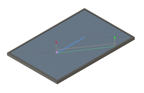
Before I could start milling the board, I had to level my mill bed. This I did by making a flat plate slightly larger than the board (110 x 170mm) in Fusion 360, and then selected a pocket milling strategy to create a surface on the MDF that would be absolutely flat.
I then postprocessed the job, converted the file to the required DOS format and fed it to the mill. I’m glad I chose to “cut air” first, with no tool in the chuck, because the first thing it did was drive the milling head down 15mm, which would have either shattered the bit or drilled right through the aluminum bed! Lesson learned: always inspect the G-code before committing the job to the mill!
The culprit was in two homing commands that Fusion added to the top and bottom of the file. I’ve commented the offending G28 line out in the code below. There was another one of these at the end of the job, which would have ruined my day then too. I’ve also added a line to lift the tool above the bed while it travels from the home point to the start of its drill down routing.
(1001)
(Machine)
(  vendor: Autodesk)
(  description: Generic 3-axis)
(T2  D=3.175 CR=0 - ZMIN=-0.2 - flat end mill)
G90 G94
G17
G21
; G28 G91 Z0  ; this would have ruined my day
G90

(Pocket1)
T2
S1000 M3
G54
M8

G0 Z15.1 ; move up away from surface
I commented out the other two G28 lines from the tail end of the file and added the usual line to the end of the file to send the milling head back to the zero position ready to start again.
G0 Z15.1
M9
; G28 G91 Z0
G90
: G28 G91 X0 Y0
G90
M5
G00X0Y0Z15          ; go back to zero position
M30
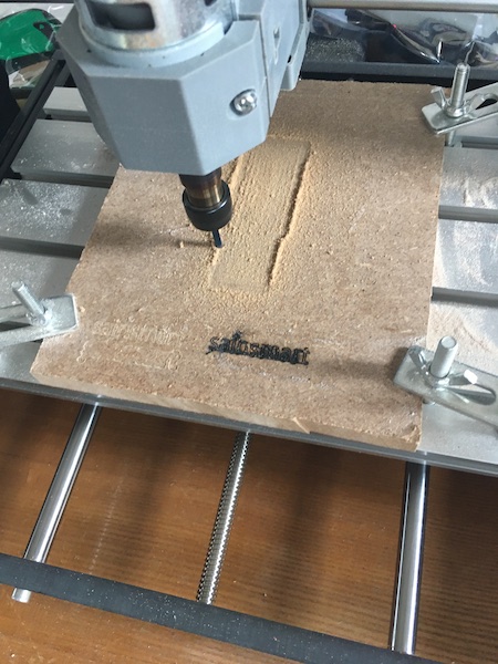
Then I converted the file to DOS and fed the CNC machine the commands. It started out well:
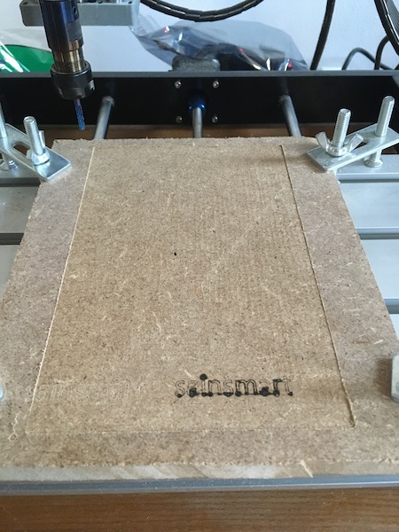
And all’s well that ends well:
Manufacturing the Board
I’m getting better at board manufacture now with practice. I still hate the Eagle output silliness, but I have slowly come to an arrangement which is bringing some peace to the house. The workflow looks like this:
- Finalise the board and ratsnest the copper popur into place.
- Export the file as an image, with 1500 dpi resolution.
- Use the dimension tool to size the outside of the copper pour on the trace (in x and y). Write that down.
- Import the image into GIMP.
- Cut the image to exactly the edges of the copper pour.
- Scale the image (image menu)
- Write down the calibration factor in mm/pixel.
- Export the image as a .PNG file
- Undo the changes
- Cut the image to exactly the border of the board.
- Apply the calibration that was written down in step 7.
- Erase everything out of the middle of the board, leaving a black rim.
- Export the image as a .PNG file (obviously with a different name).
- Close GIMP
- Drink gin.
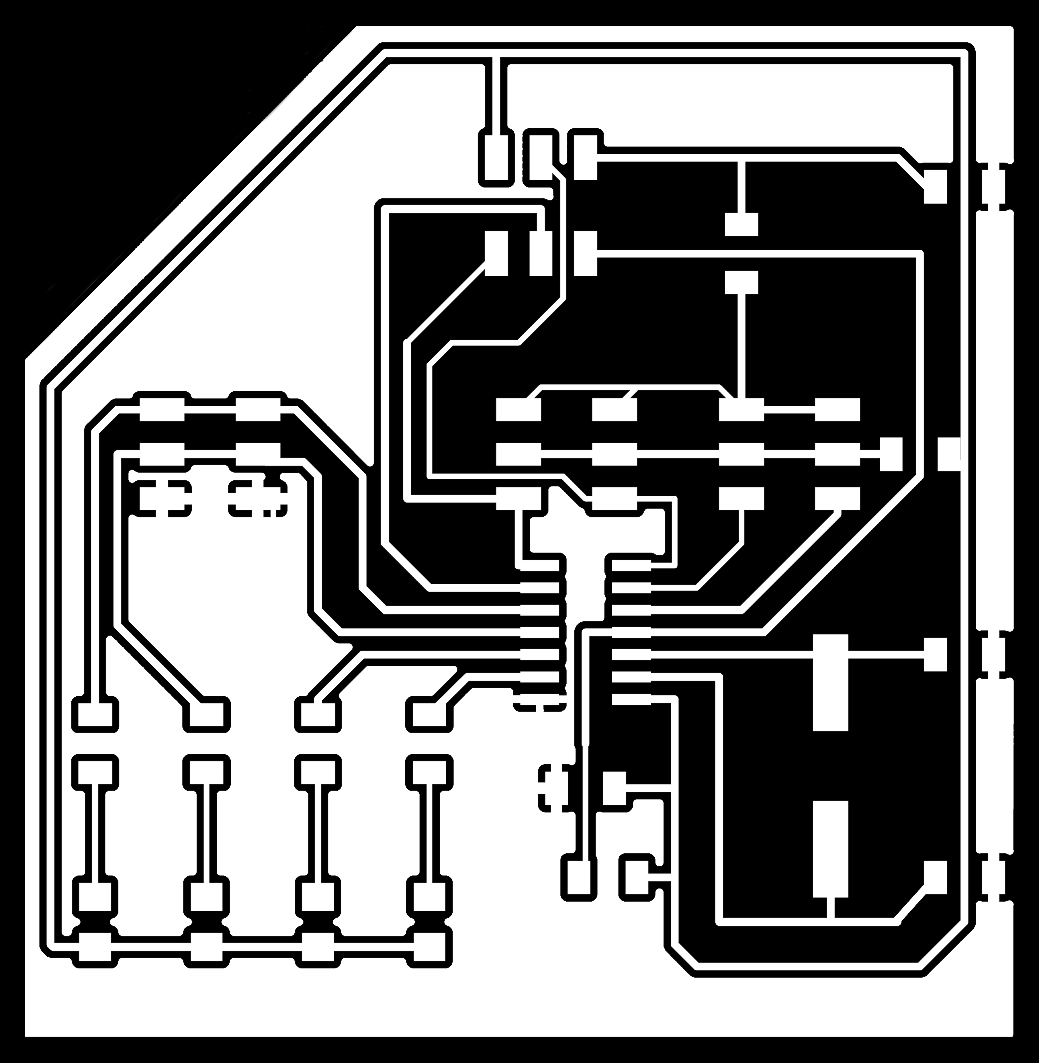
The resulting images are shown here:

Scaled PNGs in hand, the next step is to run them through FabModules. Here I followed the procedure described in the Week 05 Group Assignment and milled the board on the Genmitsu. The cutting went ok and produced the following:

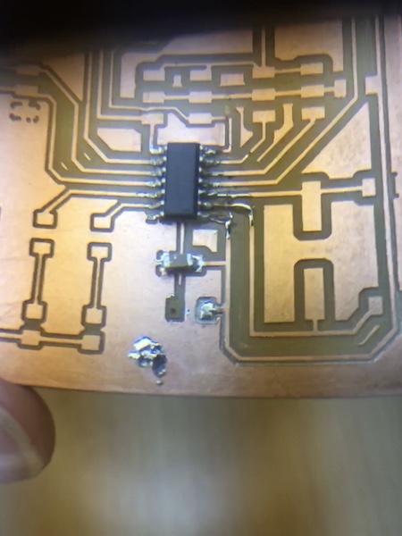
I cleaned up the board with a bit of sandpaper and was quite proud of the result. Pride does however come before a fall. In the course of sanding the surface, I dislodged some swarf which got caught somewhere between the Vcc trace and Ground and shorted them out. I didn’t notice until after I’d soldered the IC in place, and then it just got ugly as I tried to unsolder the IC… I ended up breaking one of the traces and making a mess of the pads for the capacitor and resistor as shown below (photo taken through the big magnifying glass I use for soldering).
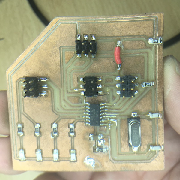
I managed some relatively secure repairs using some copper strands from a bit of stranded extension cord wire. I ended up having to make seven such band-aids in the end, and since we were short a zero-Ohm resistor, I had to make an insulated jumper out of a bit of PVC-coated wire. In testing, I also short circuited the 2nd LED in from the left, and so had to unsolder and replace that, which resulted in a further pad coming loose, but since the trace didn’t break this time, I didn’t need another band-aid. The end result looks like this:
Smoke Test
I wired the new board to my UglyDuckling FabISP and connected the hub to the Mac. No smoke, no reset of the hub. We’re good to go.
To burn the fuses, I used the Arduino IDE with settings appropriate for this board:
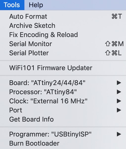
The “avrdude done. Thanks.” line was good to see.
Testing with Servos
Making three servos on an AtTiny is not just a question of changing a setting in a library. None of the libraries I tried would do anything with that third pin. The ATtiny pinout shows four PWM pins, but the datasheet only really talks about two. I spent some confusing time trying to figure out the datasheet when my instructor threw a suggestion at me from another Arduino forum post. This fellow “tylernt” has essentially built what I want to make, but done it completely with an ATtiny. I dug through his code and cut out the bits that communicate with the servos. The result was this sketch and the following excitement:
Then, just to be greedy, I added a fourth motor and some flashing LEDs:
The secret to Tyler’s code is that it controls the servos directly, without relying on any libraries (though I suppose his collection of subroutines could be termed a “library” of sorts). The reduced overhead will be crucial later when I go to add communication to the ATtiny. In the first parts of his code, he sets up some parameters, including some calibration values which determine the length of the PWM pulses to produce specific angles. The magic is in the “setupServos()” subroutine, where he sets the registers. I don’t completely understand what he’s doing here, but I get that it’s based on the PWM signal standard for servo control. There’s then a piece I don’t understand at all which does something with the timers. The setup and loop procedures are straightforward, though I will need to explore these a bit more. There’s something in the way the timers work that requires the loop to restart before the servo can be moved to a new position. Not a big deal, but something to take into account in the design of the next bit of code.
A first go at a rowing movement is shown below:
Now that it moves, the next step is to control the motion with a microswitch. I soldered some jumper wires onto the switch and plugged it into the fourth header, connected to pin 8 (arduino numbering). A quick update to the code made the movement dependent on the state of the switch. It worked exactly as expected - see for yourself:
The sketch is here
Group Assignment
Our group assignment for this week can be found here